Panneau à clic Pression 11
Overview
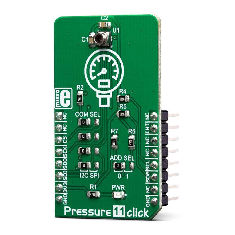
Le Pressure 11 Click Board™ est un baromètre numérique sur Click Board™. Pressure 11 est équipé du LPS33HW, un capteur de pression piézorésistif absolu, fabriqué selon une technologie propriétaire. Ce capteur offre de nombreux avantages, notamment une faible consommation d'énergie, une haute résolution des données de pression, une compensation thermique intégrée, un tampon FIFO avec plusieurs modes de fonctionnement, une mesure de température, etc.
La caractéristique la plus distinctive de ce capteur est sa capacité à mesurer la pression dans une large plage entre 260 et 1260 hPa, offrant des lectures calibrées sur l'interface numérique SPI ou I2C.
The pressure sensor contains protective gel, preventing water or humidity to damage the circuit. Additionally, it is protected from overpressure, allowing it to withstand pressure peaks up to 20x its measurement range. These features make the Pressure 11 Click Board™ a perfect tool for development of various pressure-based applications, especially when low power consumption is required: portable weather stations, IoT and other battery-operated pressure-related applications, wearables, and similar.
HOow Does The Pressure 11 Click Board™ Work?
The Pressure 11 Click Board™ features the LPS33HW, an absolute digital output barometer IC in water-resistant package, from STMicroelectronics. It can be used to measure absolute pressure values from 260 - 1260hPa. The sensor can be exposed up to 2MPa of pressure peaks, without causing any permanent damage. However, prolonged exposure to such high pressure can affect the reliability and accuracy of the sensor.
The LPS33HW IC comprises a piezoresistive MEMS and an ASIC. The MEMS consists of a suspended membrane manufactured using a proprietary technology, developed by ST. The piezoresistive elements on the membrane form a Wheatstone bridge. By applying a pressure, the balance of the bridge is disturbed, which causes a proportional voltage to appear on its output. The output of the Wheatstone bridge is then processed by the ASIC, which outputs conditioned and factory-calibrated data over the SPI or I2C interface, in 24-bit, two's complement format.
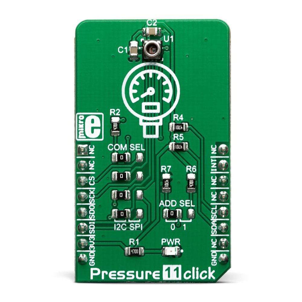
The Pressure 11 Click Board™ supports both SPI and I2C communication interfaces, allowing it to be used with a wide range of different MCUs. The communication interface can be chosen by moving SMD jumpers grouped under the COM SEL to an appropriate position (SPI or I2C). The slave I2C address can also be configured by a SMD jumper, when the Click board™ is operated in the I2C mode: a SMD jumper labeled as ADD SEL is used to set the least significant bit (LSB) of the I2C address. When set to 1, the 7-bit I2C slave address becomes 0b1011101x. If set to 0, the address becomes 0b1011100x. The last digit (x) is the R/W bit.
One of distinctive features of the LPS33HW is a highly configurable FIFO buffer, with 32 slots of 40-bit data, allowing to buffer both pressure and temperature readings. The FIFO buffer can be configured to work in one of several available modes, offering a great flexibility. Along with the extensive interrupt engine which can signal several FIFO-related events over a dedicated INT_DRDY pin, the FIFO buffer can be very useful for writing an optimized MCU firmware.
Besides FIFO-related events, the extensive interrupt engine of the LPS33HW IC can be configured to signal several other events over a dedicated INT_DRDY pin, including events when a programmable low or high threshold level is exceeded, and events when there is a data ready to be read from the output. The INT_DRDY pin of the LPS33HW IC is routed to the mikroBUS™ INT pin. Its active state (active LOW or active HIGH) is freely configurable.
Pressure data at the output is in 24-bit, two's complement format. Thanks to the highly advanced ASIC, the output is already formatted in physical units, with minimum operations required from the host MCU. Since the sensitivity is 4096 LSB/hPa, the output result should be divided by 4096 in order to obtain the value in hPa units. Temperature data is in 16-bit two's complement format, and it does not require any conversions. The sensitivity of the temperature sensor is 100 LSB/⁰C so the output result should be divided by 100 in order to obtain the value in ⁰C units. ASIC also offers some other processing functions such as the lowpass filtering of the output data, which helps reducing the inconsistencies due to sudden pressure changes.
The Pressure 11 Click Board™ uses both I2C and SPI communication interfaces. It is designed to be operated only with 3.3V logic levels. A proper logic voltage level conversion should be performed before the Click board™ is used with MCUs with logic levels of 5V.
SPECIFICATIONS
Type | Pressure |
Applications | The Pressure 11 Click Board™ is a perfect tool for development of various pressure-based applications, especially when low power consumption is required: portable weather stations, IoT and other battery-operated pressure-related applications, wearables, and similar. |
On-board modules | LPS33HW, an absolute digital output barometer IC in water-resistant package, from STMicroelectronics. |
Key Features | Built in ASIC for output data processing, 24-bit conversion, low count of external components required, water-proof casing offers reliability and long-term stability, extensive programmable interrupt engine, advanced FIFO buffer with several operating modes, etc. |
Interface | I2C,SPI |
Compatibility | mikroBUS |
Click board size | M (42.9 x 25.4 mm) |
Input Voltage | 3.3V |
PINOUT DIAGRAM
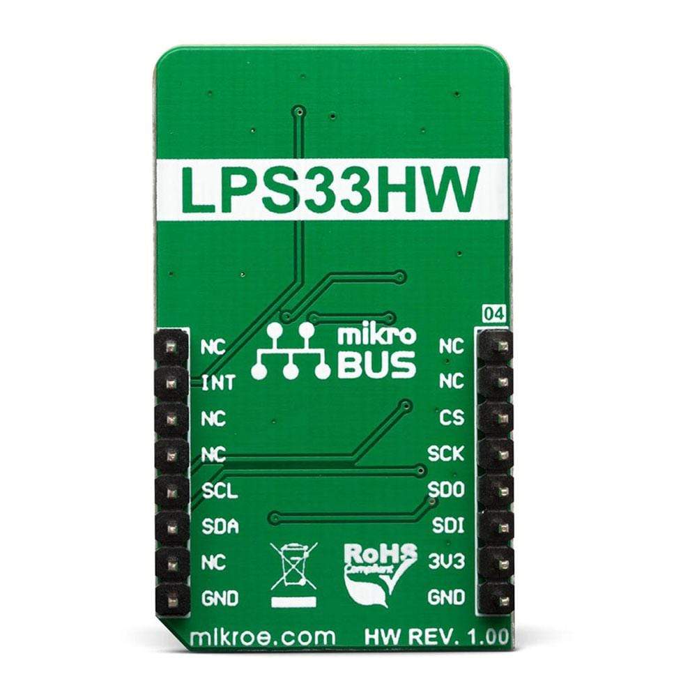
This table shows how the pinout on the Pressure 11 Click Board™ corresponds to the pinout on the mikroBUS™ socket (the latter shown in the two middle columns).
Notes | Pin | Pin | Notes | ||||
---|---|---|---|---|---|---|---|
NC | 1 | AN | PWM | 16 | NC | ||
NC | 2 | RST | INT | 15 | INT | Interrupt | |
SPI Chip Select | CS | 3 | CS | RX | 14 | NC | |
SPI Clock | SCK | 4 | SCK | TX | 13 | NC | |
SPI Data OUT | SDO | 5 | MISO | SCL | 12 | SCL | I2C Clock |
SPI Data IN | SDI | 6 | MOSI | SDA | 11 | SDA | I2C Data |
Power Supply | 3.3V | 7 | 3.3V | 5V | 10 | NC | |
Ground | GND | 8 | GND | GND | 9 | GND | Ground |
ONBOARD SETTINGS AND INDICATORS
Label | Name | Default | Description |
---|---|---|---|
LD1 | PWR | - | Power LED indicator |
JP1, JP4 | COM SEL | Left | Communication interface selection: left position I2C, right position SPI |
JP5 | ADDR SEL | Left | Slave I2C address LSB selection: left position 0, right position 1 |
RPRESSURE 8 CLICK ELECTRICAL SPECIFICATIONS
Description | Min | Typ | Max | Unit |
---|---|---|---|---|
Pressure range | 260 | - | 1260 | hPa |
Operating temperature range | -40 | - | +85 | ˚C |
Output Data rate | 1 | - | 75 | sps |
Software Support
We provide a library for the Pressure 11 Click Board™ on our LibStock page, as well as a demo application (example), developed using MikroElektronika compilers. The demo can run on all the main MikroElektronika development boards.
Library Description
The library initializes and defines the I2C or SPI bus driver and drivers that offer a choice for writing data in register and reads data form register. The library includes function for read Pressure data in mBar and Temperature data in C. The user also has the function for read device ID and function for read interrupt state.
Key Functions
float pressure11_getPressure()
- Functions for pressure reading.float pressure11_getTemperature()
- Functions for temperature reading.
Example Description
The application is composed of the three sections :
- System Initialization - Initializes SPI module and sets CS pin as OUTPUT and INT pin as INPUT.
- Application Initialization - Initializes SPI driver and checks chip ID.
- Application Task - Reads Pressure and Temperature values and displays it on UART LOG.
void applicationTask() { float Temperature; float Pressure; Temperature = pressure11_getTemperature(); FloatToStr(Temperature,demoText); mikrobus_logWrite( "Temperature: ", _LOG_TEXT ); mikrobus_logWrite( demoText, _LOG_TEXT ); mikrobus_logWrite( " C", _LOG_LINE ); Pressure = pressure11_getPressure(); FloatToStr(Pressure,demoText); mikrobus_logWrite( "Pressure: ", _LOG_TEXT ); mikrobus_logWrite( demoText, _LOG_TEXT ); mikrobus_logWrite( " hPa (mBar)", _LOG_LINE ); mikrobus_logWrite( "----------------------", _LOG_LINE ); Delay_ms( 500 ); } The full application code, and ready to use projects can be found on our LibStock page.
Other mikroE Libraries used in the example:
I2C
SPI
Conversions
Additional Notes and Information
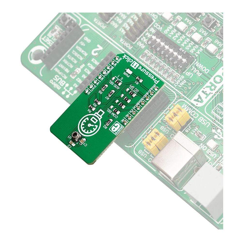
Depending on the development board you are using, you may need a USB UART click, USB UART 2 click or RS232 click to connect to your PC, for development systems with no UART to USB interface available on the board. The terminal available in all MikroElektronika compilers, or any other terminal application of your choice, can be used to read the message.
MIKROSDK
The Pressure 11 Click Board™ is supported with mikroSDK - MikroElektronika Software Development Kit. To ensure proper operation of mikroSDK compliant click board demo applications, mikroSDK should be downloaded from the LibStock and installed for the compiler you are using.
Frequently Asked Questions
Have a Question?
Be the first to ask a question about this.