


Mikroelektronika d.o.o.
Tableau à clic One Shot
Tableau à clic One Shot
SKU: MIKROE-3877
Impossible de charger la disponibilité du service de retrait


Overview
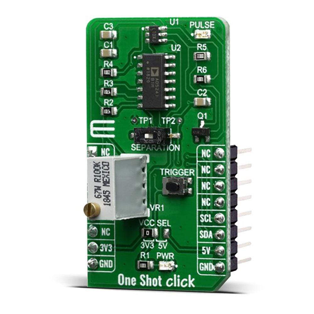
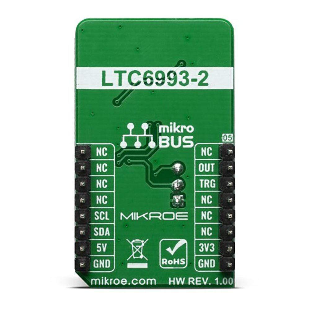
The One Shot Click Board™ is equipped with the monostable multivibrator (also known as a “one-shot” pulse generator) with a programmable pulse width of 1μs to 33.6 seconds. The used LTC6993-2 is part of the TimerBlox® family of versatile silicon timing devices, from Analog Devices. In addition to this, the One Shot Click also offers configurability for either positive or negative output pulse, fast recovery time, 70μA supply current, CMOS output driver 20mA sources/sinks and many more useful features, which makes this Click Board™ an ideal choice for applications such as watchdog timers, frequency discriminators, missing pulse detection, envelope detection and more.
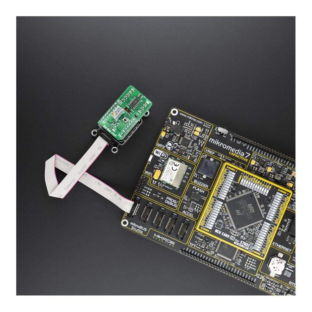
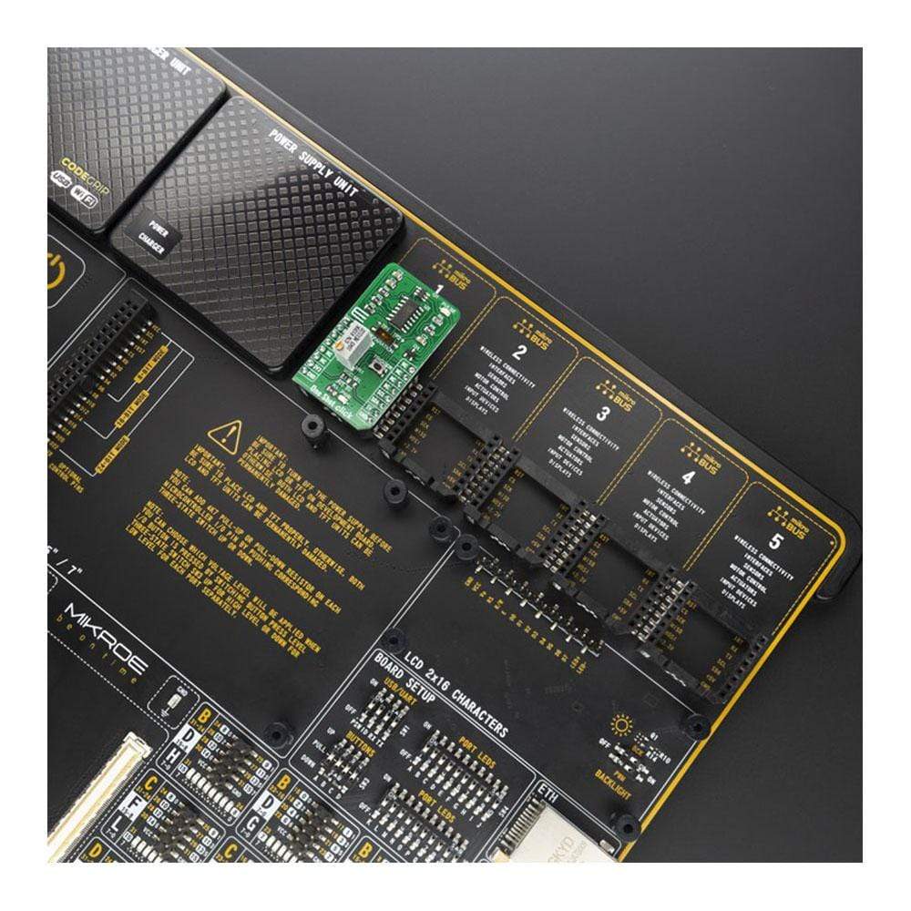
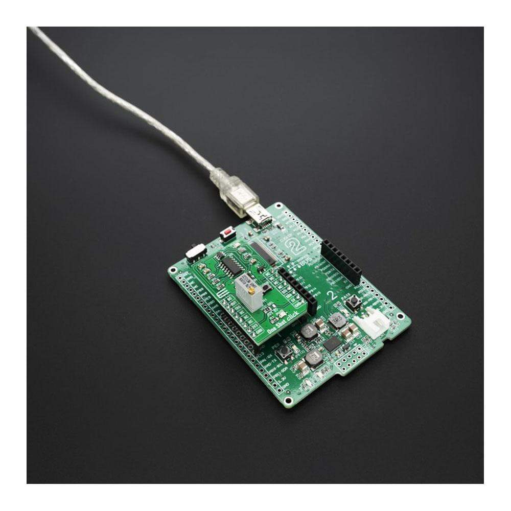
The One Shot Click Board™ is supported by a mikroSDK compliant library, which includes functions that simplify software development. This Click Board™ comes as a fully tested product, ready to be used on a system equipped with the mikroBUS™ socket.
Downloads
Le One Shot Click Board™ est équipé d'un multivibrateur monostable (également appelé générateur d'impulsions « one-shot ») avec une largeur d'impulsion programmable de 1 μs à 33,6 secondes. Le LTC6993-2 utilisé fait partie de la famille TimerBlox® de dispositifs de synchronisation en silicium polyvalents, d'Analog Devices. En plus de cela, le One Shot Click offre également une configurabilité pour une impulsion de sortie positive ou négative, un temps de récupération rapide, un courant d'alimentation de 70 μA, des sources/puits de sortie CMOS de 20 mA et de nombreuses autres fonctionnalités utiles, ce qui fait de ce Click Board™ un choix idéal pour des applications telles que les temporisateurs de surveillance, les discriminateurs de fréquence, la détection d'impulsions manquantes, la détection d'enveloppe et bien plus encore.
Le One Shot Click Board™ est pris en charge par une bibliothèque compatible mikroSDK, qui comprend des fonctions qui simplifient le développement logiciel. Ce Click Board™ est un produit entièrement testé, prêt à être utilisé sur un système équipé du socket mikroBUS™.
| General Information | |
|---|---|
Part Number (SKU) |
MIKROE-3877
|
Manufacturer |
|
| Physical and Mechanical | |
Weight |
0.019 kg
|
| Other | |
EAN |
8606018719341
|
Frequently Asked Questions
Have a Question?
Be the first to ask a question about this.