


Mikroelektronika d.o.o.
Carte à clic ADC
Carte à clic ADC
SKU: MIKROE-922
Impossible de charger la disponibilité du service de retrait
Overview
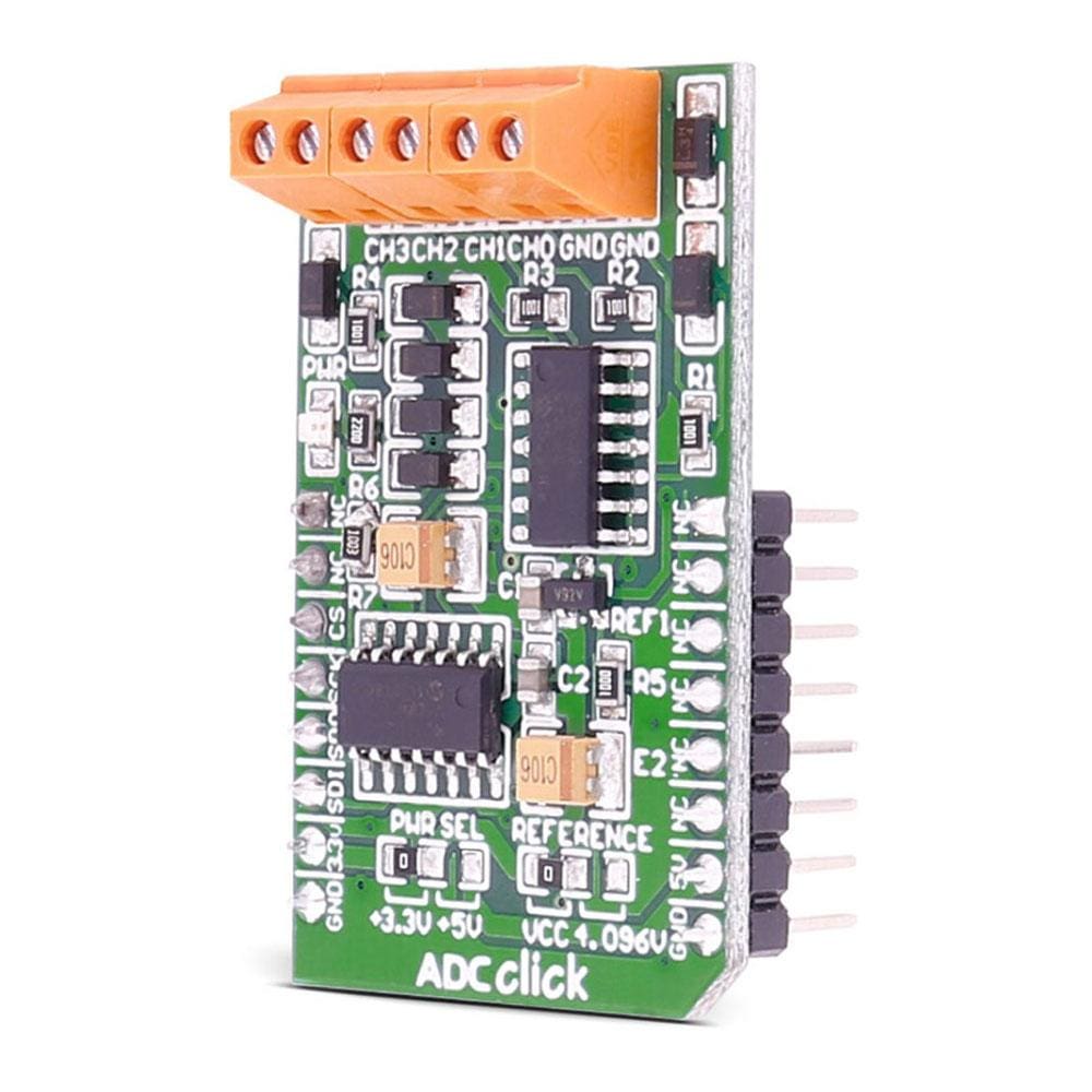
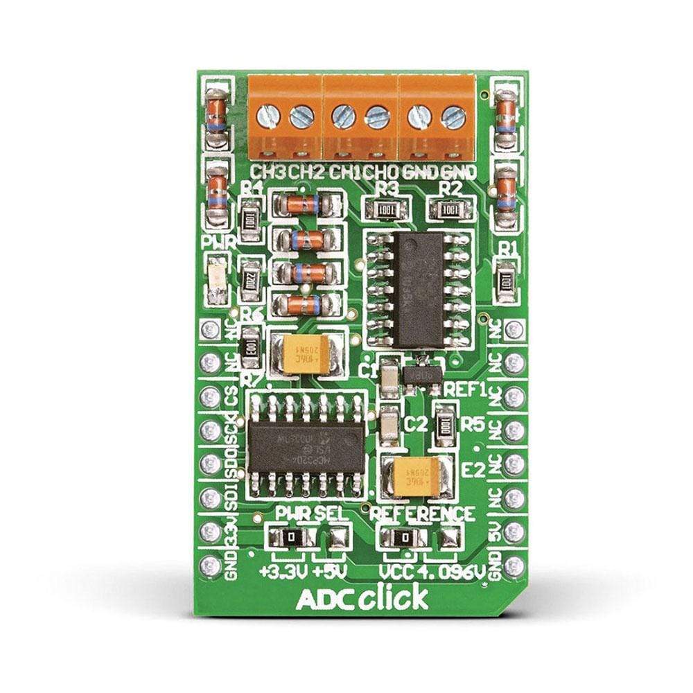
The ADC Click Board™ carries the MCP3204 12-bit Analog-to-Digital converter. The Click Board™ is designed to run on 3.3V by default. Place PWR SEL SMD jumper to 5V position if used with 5V systems. It communicates with the target microcontroller over SPI interface.
Downloads
L' ADC Click Board™ est équipé du convertisseur analogique-numérique 12 bits MCP3204. Le Click Board™ est conçu pour fonctionner sur 3,3 V par défaut. Placez le cavalier PWR SEL SMD sur la position 5 V s'il est utilisé avec des systèmes 5 V. Il communique avec le microcontrôleur cible via l'interface SPI.
| General Information | |
|---|---|
Part Number (SKU) |
MIKROE-922
|
Manufacturer |
|
| Physical and Mechanical | |
Weight |
0.03 kg
|
| Other | |
EAN |
8606015073231
|
Frequently Asked Questions
Have a Question?
Be the first to ask a question about this.