


Mikroelektronika d.o.o.
Tableau de clic Accel 29
Tableau de clic Accel 29
Impossible de charger la disponibilité du service de retrait
Key Features:
- Plage de mesure ±200g, faible consommation d'énergie, bande passante sélectionnable par l'utilisateur, résolution de sortie fixe de 13 bits, interface sélectionnable, système de gestion de mémoire intégré avec technologie FIFO, interruption, etc.
- Basé sur l'ADXL314 - accéléromètre à trois axes d'Analog Devices
- Peut être utilisé pour de multiples applications telles que les fonctions activées par le mouvement, la détection des chocs, la détection d'événements à force élevée, etc.
- mikroBUS : interfaces I2C et SPI
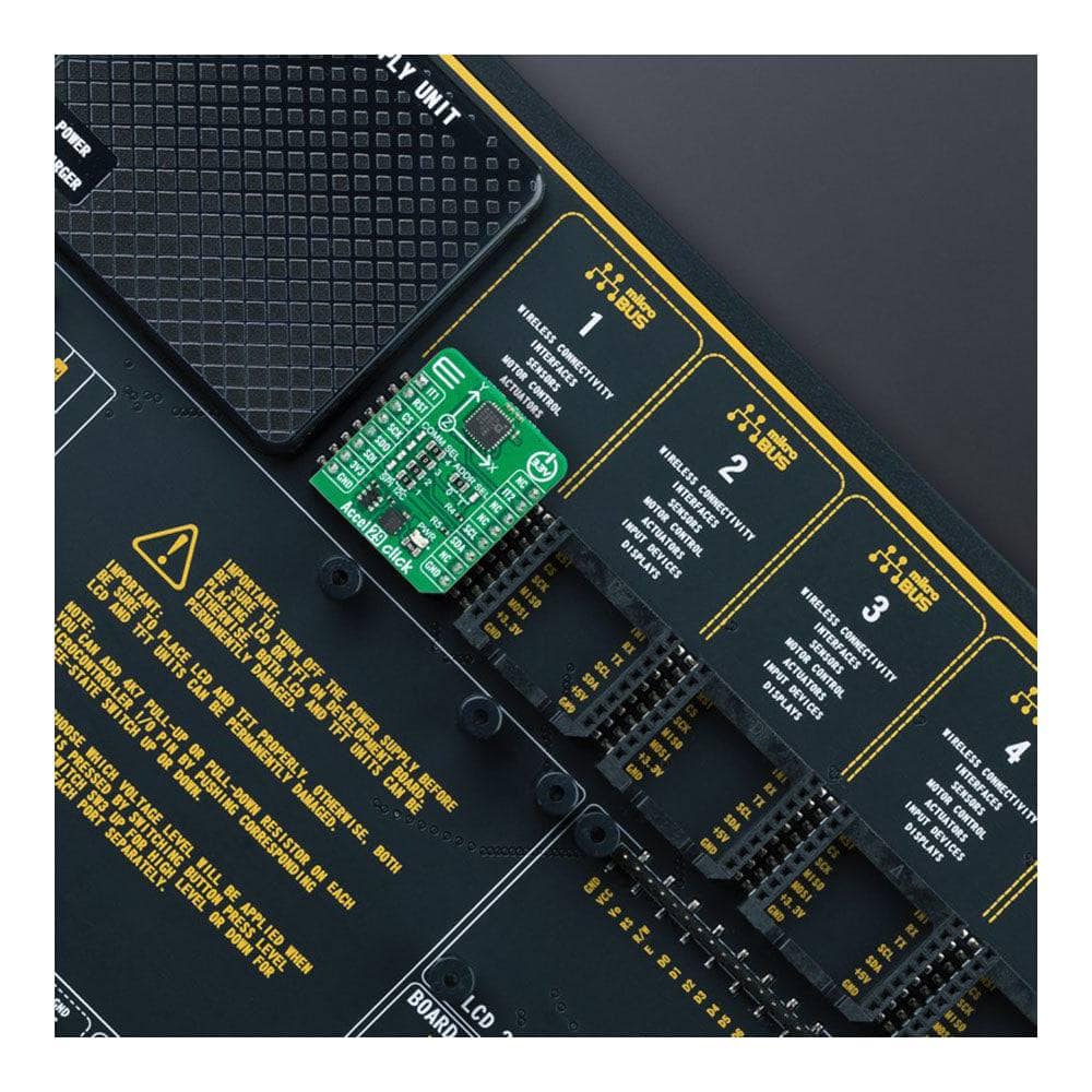
Présentation de l'Accel 29 Click Board™ : une centrale de détection d'accélération compacte
Découvrez le niveau supérieur en matière de détection d'accélération avec l'Accel 29 Click Board™ ! Cette carte complémentaire compacte est équipée de l'ADXL314 de pointe, un accéléromètre à trois axes ±200 g d'Analog Devices, leader du secteur. Ses données de sortie numériques 16 bits et son interface hôte configurable, prenant en charge les communications série SPI et I2C, en font la solution parfaite pour vos fonctions activées par le mouvement, la détection de chocs, la détection d'événements à force élevée, etc.
Maximisez l'efficacité grâce à la gestion intégrée de la mémoire
Doté d'un système de gestion de mémoire intégré avec un tampon FIFO à 32 niveaux, l'Accel 29 Click Board™ minimise l'activité du processeur hôte et réduit la consommation d'énergie globale du système. Ses modes basse consommation permettent une gestion intelligente de l'alimentation basée sur le mouvement avec détection de seuil et mesure d'accélération active avec une dissipation d'énergie incroyablement faible.
Développez en toute simplicité : bibliothèque compatible avec mikroSDK
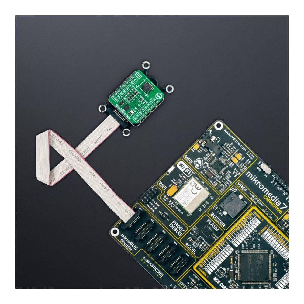
S'appuyant sur une bibliothèque compatible mikroSDK, l'Accel 29 Click Board™ simplifie le développement logiciel grâce à ses fonctions prédéfinies. Ce produit entièrement testé est prêt à être utilisé immédiatement sur un système équipé du socket mikroBUS™, vous permettant de vous concentrer sur ce qui compte le plus : créer des applications innovantes avec des capacités de détection d'accélération inégalées.
How Does The Accel 29 Click Board™ Work?
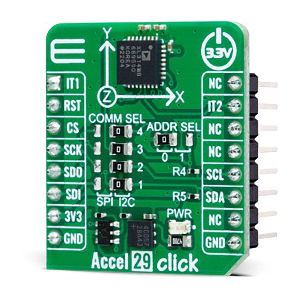
The Accel 29 Click Board™ is based on the ADXL314, a complete three-axis ±200g acceleration measurement system from Analog Devices, operating at low power levels. The ADXL314 measures both dynamic accelerations resulting from motion or shock and static accelerations, such as gravity. It provides digital output data formatted as 16-bit, with acceleration reported digitally through a configurable and selectable serial interface. The ADXL314 automatically modulates its power consumption proportionately to its output data rate. If additional power savings are desired, it also offers lower power modes, enabling intelligent motion-based power management with threshold sensing and active acceleration measurement at low power dissipation.
The ADXL314 is based on a polysilicon surface-micromachined structure built on top of a silicon wafer that suspends the structure over the surface of the wafer, providing resistance against forces due to applied acceleration. Deflection of the structure is measured using differential capacitors that consist of independent fixed plates and plates attached to the moving mass. Acceleration deflects the proof mass and unbalances the differential capacitor, producing a sensor output whose amplitude is proportional to acceleration. Phase-sensitive demodulation is used to determine the magnitude and polarity of the acceleration.
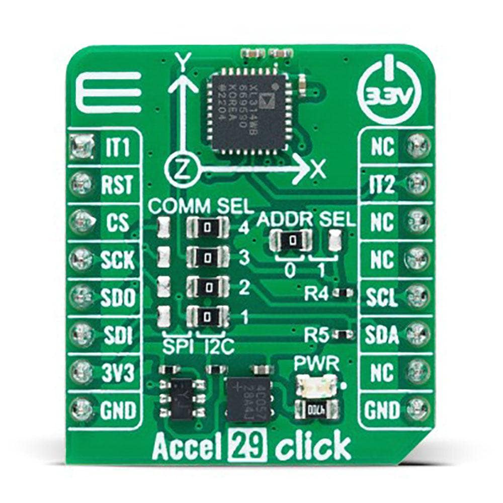
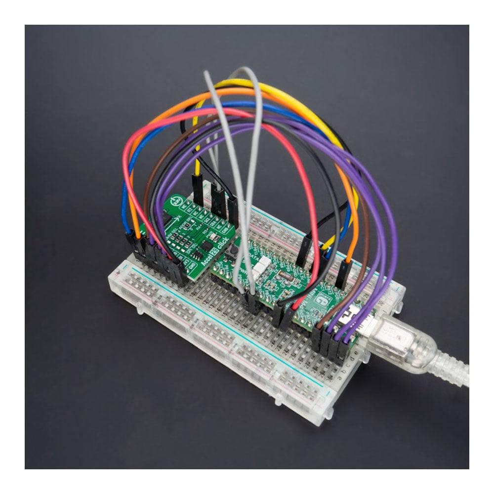
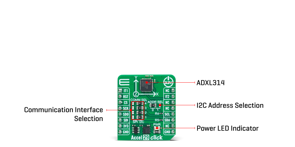
As mentioned, the acceleration data is accessed through I2C or SPI interface with a maximum frequency of 400kHz for I2C and 5MHz for SPI communication. The selection is made by positioning SMD jumpers labelled COMM SEL appropriately. Note that all the jumpers' positions must be on the same side, or the Click board™ may become unresponsive. While the I2C interface is selected, the ADXL314 allows choosing the least significant bit (LSB) of its I2C slave address using the SMD jumper labelled ADDR SEL.
This board also possesses two interrupts, IT1 and IT2, routed to, where by default, the AN and IT pins stand on the mikroBUS™ socket, entirely programmed by the user through a serial interface. They signal MCU that a motion event has been sensed.
The Accel 29 Click Board™ can only be operated with a 3.3V logic voltage level. The board must perform appropriate logic voltage level conversion before using MCUs with different logic levels. However, the Click board™ comes equipped with a library containing functions and an example code that can be used as a reference for further development.
SPECIFICATIONS
| Type | Motion |
| Applications | It can be used for multiple applications, such as motion-activated functions, shock detection, high-force event detection, and more |
| On-board modules | ADXL314 - three-axis accelerometer from Analog Devices |
| Key Features | ±200g measurement range, low power consumption, user-selectable bandwidth, fixed 13-bit output resolution, selectable interface, embedded memory management system with FIFO technology, interrupt, and more |
| Interface | I2C,SPI |
| Compatibility | mikroBUS |
| Click board size | S (28.6 x 25.4 mm) |
| Input Voltage | 3.3V |
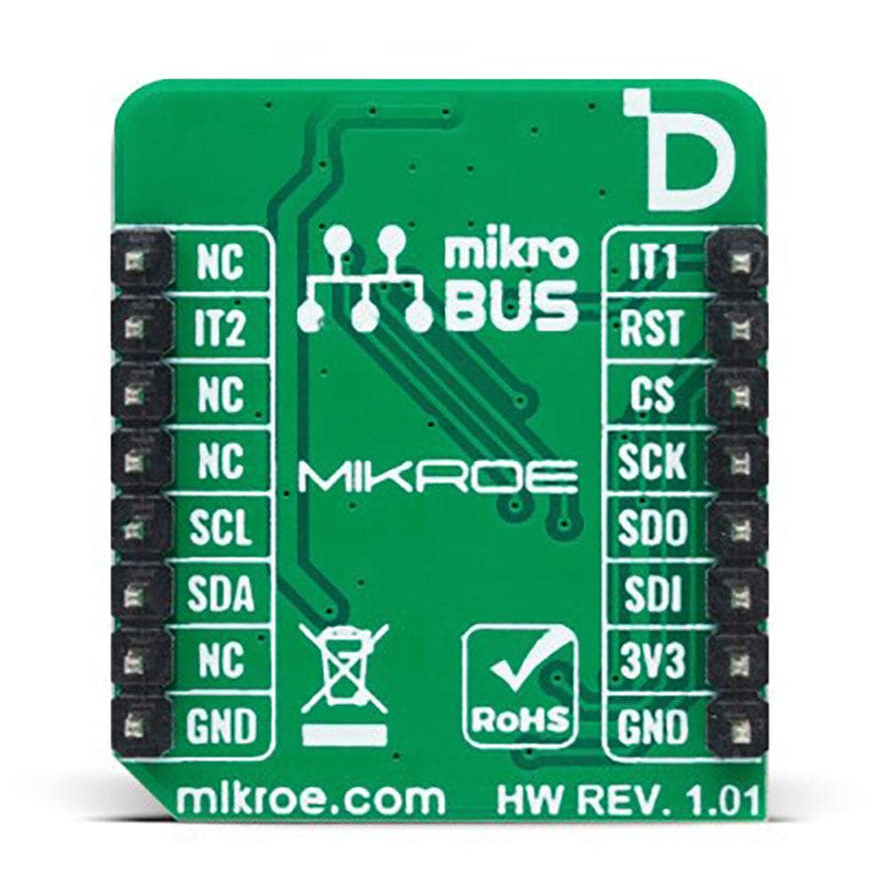
PINOUT DIAGRAM
This table shows how the pinout on f the Accel 29 Click Board™ corresponds to the pinout on the mikroBUS™ socket (the latter shown in the two middle columns).
| Notes | Pin | Pin | Notes | ||||
|---|---|---|---|---|---|---|---|
| Interrupt 1 | IT1 | 1 | AN | PWM | 16 | NC | |
| NC | 2 | RST | INT | 15 | IT2 | Interrupt 2 | |
| SPI Chip Select | CS | 3 | CS | RX | 14 | NC | |
| SPI Clock | SCK | 4 | SCK | TX | 13 | NC | |
| SPI Data OUT | SDO | 5 | MISO | SCL | 12 | SCL | I2C Clock |
| SPI Data IN | SDI | 6 | MOSI | SDA | 11 | SDA | I2C Data |
| Power Supply | 3.3V | 7 | 3.3V | 5V | 10 | NC | |
| Ground | GND | 8 | GND | GND | 9 | GND | Ground |
ONBOARD SETTINGS AND INDICATORS
| Label | Name | Default | Description |
|---|---|---|---|
| LD1 | PWR | - | Power LED Indicator |
| JP1-JP4 | COMM SEL | Right | Communication Interface Selection SPI/I2C: Left position SPI, Right position I2C |
| JP5 | ADDR SEL | Left | I2C Address Selection 0/1: Left position 0, Right position 1 |
ACCEL 29 CLICK ELECTRICAL SPECIFICATIONS
| Description | Min | Typ | Max | Unit |
|---|---|---|---|---|
| Supply Voltage | - | 3.3 | - | V |
| Acceleration Range | - | ±200 | - | g |
| Resolution | - | 13 | - | bits |
| Sensitivity | - | 20.83 | - | LSB/g |
Software Support
We provide a library for the Accel 29 Click Board™ as well as a demo application (example), developed using MikroE compilers. The demo can run on all the main MikroE development boards.
The package can be downloaded/installed directly from NECTO Studio The package Manager (recommended), downloaded from our LibStock™ or found on MikroE Github account.
Library Description
This library contains API for Acthe Accel 29 Click Board™ driver.
Key functions
-
accel29_calibrate_offsetThis function calibrates accel offset to the specified values by setting the OFSX/Y/Z registers. -
accel29_get_avg_axesThis function reads a specified number of samples for accel X, Y, and Z axis data in g and averages them.
Example Description
This example demonstrates use of the Accel 29 Click Board™ by reading and displaying the accelerometer data (X, Y, and Z axis) averaged from 100 samples.
void application_task ( void )
 {
     accel29_axes_t axes;
     if ( ACCEL29_OK == accel29_get_avg_axes ( &accel29, ACCEL29_NUM_OF_SAMPLES, &axes ) )
     {
         log_printf( &logger, " X: %.1f grn", axes.x );
         log_printf( &logger, " Y: %.1f grn", axes.y );
         log_printf( &logger, " Z: %.1f grnn", axes.z );
     }
 }
The full application code, and ready to use projects can be installed directly from NECTO Studio The package Manager (recommended), downloaded from our LibStock™ or found on MikroE Github account.
Other MikroE Libraries used in the example:
- MikroSDK.Board
- MikroSDK.Log
- Click.Accel29
Additional Notes and Information
Depending on the development board you are using, you may need USB UART Click Board™, USB UART 2 Click or RS232 Click to connect to your PC, for development systems with no UART to USB interface available on the board. UART terminal is available in all MikroE compilers.
MIKROSDK
The Accel 29 Click Board™ is supported with mikroSDK - MikroE Software Development Kit, that needs to be downloaded from the LibStock and installed for the compiler you are using to ensure proper operation of mikroSDK compliant Click board™ demo applications.
Tableau de clic Accel 29
Frequently Asked Questions
Ask a Question-
Is the Accel 29 Click Board™ ready for use on a system equipped with the mikroBUS™ socket?
Yes, the Accel 29 Click Board™ comes as a fully tested product, ready for use on a system equipped with the mikroBUS™ socket.
-
Is the Accel 29 Click Board™ easy to use for software development?
Yes, the Accel 29 Click Board™ is supported by a mikroSDK-compliant library, which includes functions that simplify software development.
-
What other applications is the Accel 29 Click Board™ suitable for?
The Accel 29 Click Board™ is also suitable for shock detection, high-force event detection, and more.
-
Can the Accel 29 Click Board™ be used for motion-activated functions?
Yes, the Accel 29 Click Board™ is suitable for multiple applications, including motion-activated functions.
-
Does the Accel 29 Click Board™ have any memory management features?
Yes, the Accel 29 Click Board™ has an integrated memory management system with a 32-level FIFO buffer. This can store data to minimize host processor activity and lower overall system power consumption.
-
What kind of host interfaces are supported by the ADXL314?
The ADXL314 supports SPI and I2C serial communication.
-
What kind of digital output data does the ADXL314 offer?
The ADXL314 offers 16-bit digital output data.
-
What is the Accel 29 Click Board™?
The Accel 29 Click Board™ is an add-on board that features an acceleration sensor. Specifically, it includes the ADXL314, which is a three-axis ±200g accelerometer from Analog Devices.