

Mikroelektronika d.o.o.
Carte de commande LED 17 Click
Carte de commande LED 17 Click
SKU: MIKROE-5565
Impossible de charger la disponibilité du service de retrait


Key Features
Overview
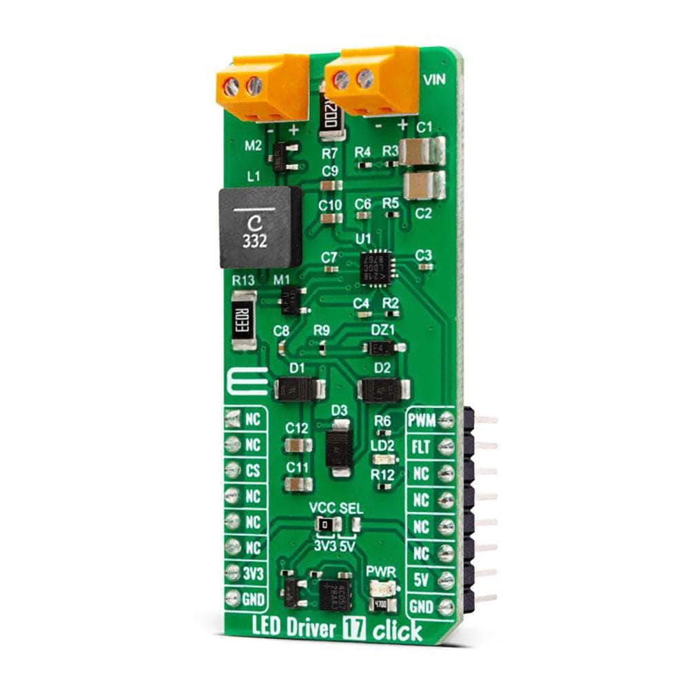
Introducing the LED Driver 17 Click Board™ - The Ultimate Solution for LED Control
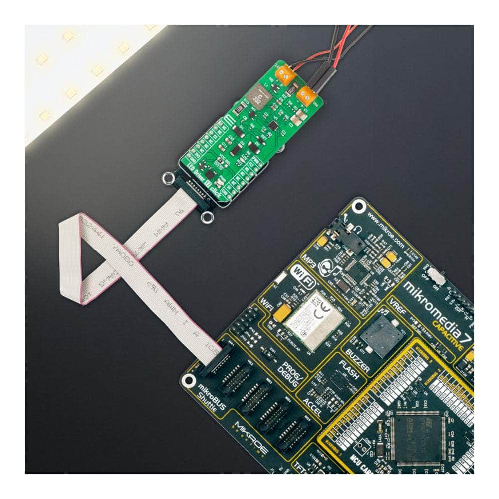
Discover the LED Driver 17 Click Board™, a compact and versatile add-on board that offers a simple yet powerful solution for controlling multiple LEDs in various applications. Whether you're working on architectural lighting, general lighting, or just exploring your creativity with LEDs, this is the perfect choice for you!
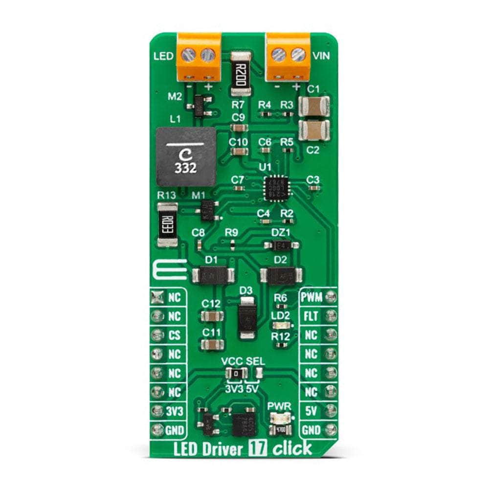
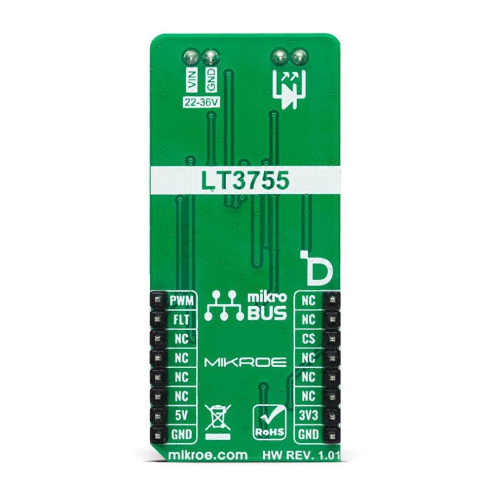
Featuring the LTR3755 - A High-Efficiency DC/DC Controller from Analog Devices
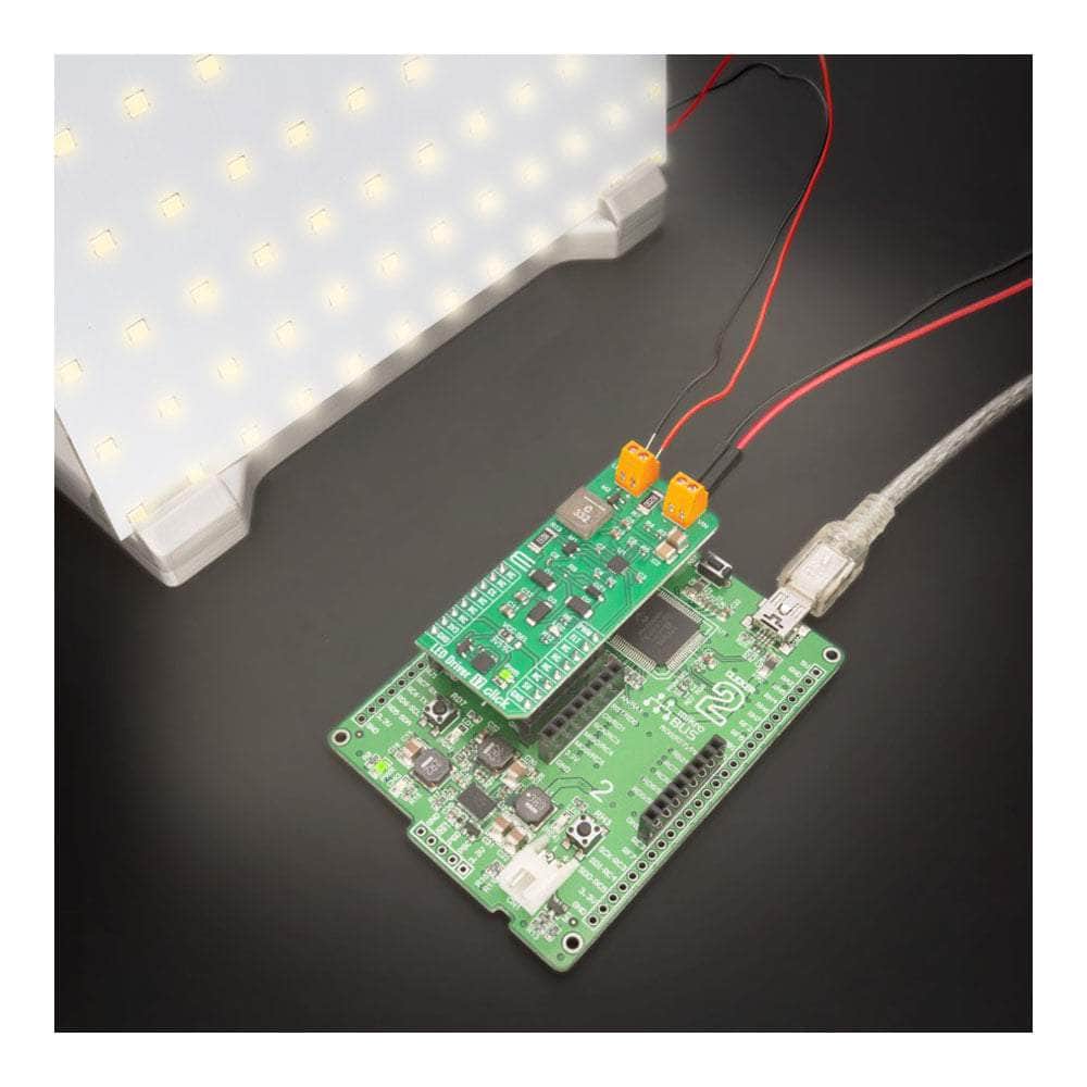
At the heart of this remarkable board is the LTR3755, a highly efficient DC/DC controller designed to operate as a constant-current source. With the ability to easily drive high-current LEDs and onboard low-side external N-channel power MOSFETs, the LED Driver 17 Click Board™ ensures stable operation over a wide supply range.
Comprehensive LED Protection Features
Designed with user safety in mind, the LED Driver 17 Click Board™ offers several essential protection features for your LEDs, including overvoltage and overcurrent protection. Plus, the frequency adjust pin allows you to program the switching frequency from 100kHz to 1MHz, optimizing efficiency and performance to suit your needs.
Supported by mikroSDK - Simplifying Software Development
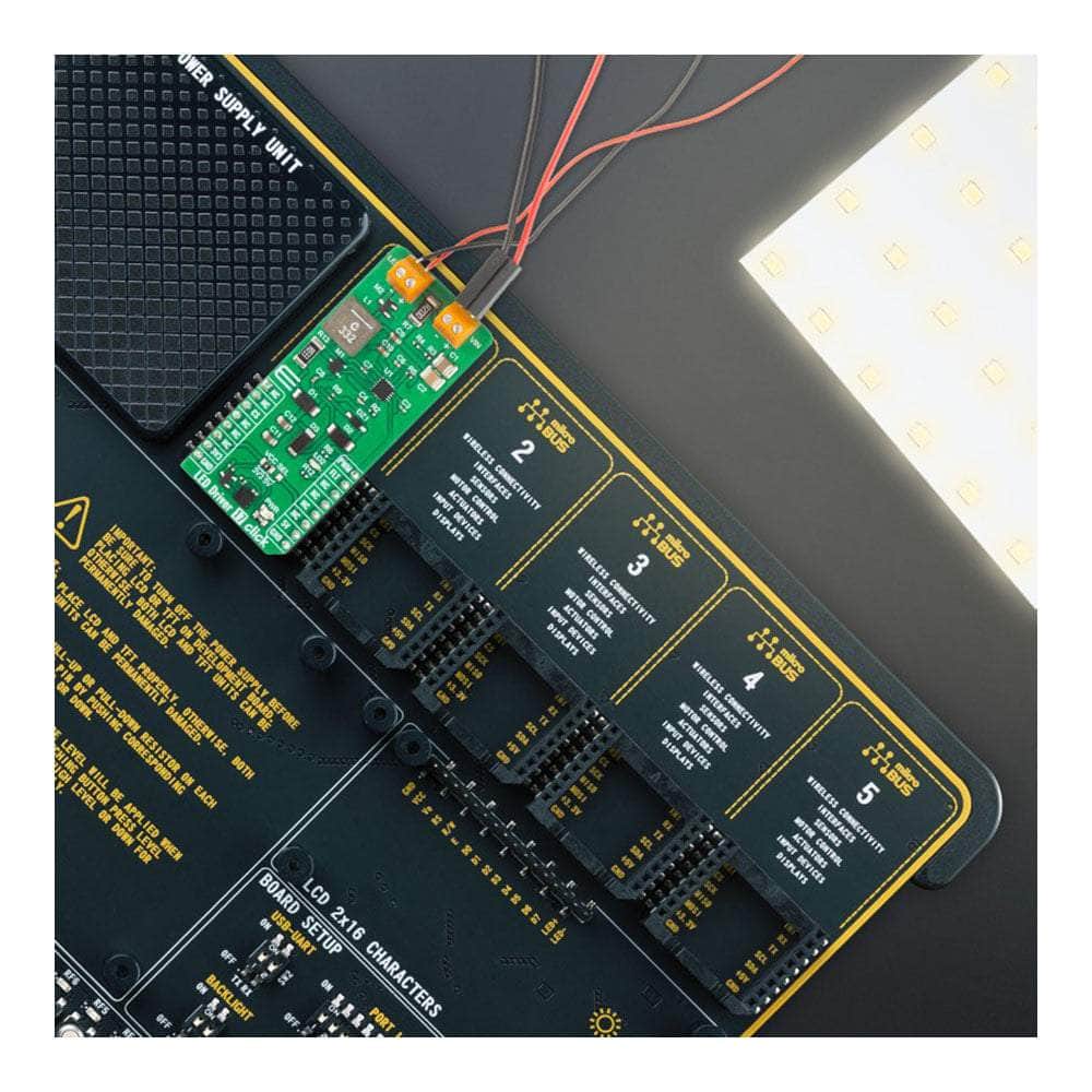
When it comes to software development, the LED Driver 17 Click Board™ has you covered. It is supported by a mikroSDK-compliant library, which includes functions that make software development a breeze. This Click board™ comes as a fully tested product, ready to be integrated into any system equipped with the mikroBUS™ socket.
A Versatile Choice for Hobbyists and Professionals Alike
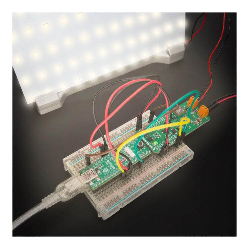
Whether you're a hobbyist or a professional, the LED Driver 17 Click Board™ is the ideal choice for controlling multiple LEDs in various settings. With its comprehensive features, ease of use, and reliable performance, this Click board™ will undoubtedly enhance your LED projects and applications.
Downloads
Présentation du LED Driver 17 Click Board™ - La solution ultime pour le contrôle des LED
Découvrez le LED Driver 17 Click Board™, une carte complémentaire compacte et polyvalente qui offre une solution simple mais puissante pour contrôler plusieurs LED dans diverses applications. Que vous travailliez sur l'éclairage architectural, l'éclairage général ou que vous exploriez simplement votre créativité avec les LED, c'est le choix parfait pour vous !
Présentant le LTR3755 - Un contrôleur CC/CC à haute efficacité d'Analog Devices
Au cœur de cette carte remarquable se trouve le LTR3755, un contrôleur DC/DC hautement efficace conçu pour fonctionner comme une source de courant constant. Avec la possibilité de piloter facilement des LED à courant élevé et des MOSFET de puissance à canal N externes côté bas intégrés, la LED Driver 17 Click Board™ assure un fonctionnement stable sur une large plage d'alimentation.
Fonctions complètes de protection des LED
Conçu pour la sécurité de l'utilisateur, le LED Driver 17 Click Board™ offre plusieurs fonctions de protection essentielles pour vos LED, notamment une protection contre les surtensions et les surintensités. De plus, la broche de réglage de fréquence vous permet de programmer la fréquence de commutation de 100 kHz à 1 MHz, optimisant ainsi l'efficacité et les performances en fonction de vos besoins.
Prise en charge par mikroSDK - Simplification du développement logiciel
En matière de développement logiciel, le LED Driver 17 Click Board™ est fait pour vous. Il est pris en charge par une bibliothèque compatible mikroSDK, qui comprend des fonctions qui facilitent le développement logiciel. Ce Click board™ est un produit entièrement testé, prêt à être intégré dans n'importe quel système équipé de la prise mikroBUS™.
Un choix polyvalent pour les amateurs et les professionnels
Que vous soyez amateur ou professionnel, le LED Driver 17 Click Board™ est le choix idéal pour contrôler plusieurs LED dans différents environnements. Avec ses fonctionnalités complètes, sa facilité d'utilisation et ses performances fiables, ce Click board™ améliorera sans aucun doute vos projets et applications LED.
| General Information | |
|---|---|
Part Number (SKU) |
MIKROE-5565
|
Manufacturer |
|
| Physical and Mechanical | |
Weight |
0.02 kg
|
| Other | |
EAN |
8606027384936
|
Frequently Asked Questions
Have a Question?
Be the first to ask a question about this.