Tableau de clic Fan 5
Key Features
- Vitesse du ventilateur proportionnelle à la température, bruit réduit, entraînement du ventilateur 5 V et 12 V, technologie FanSense™ protégeant contre les pannes de ventilateur, entraînement du ventilateur PWM, interface I2C, thermistance sélectionnable, indicateur LED de défaut, etc.
- Basé sur le TC654 - contrôleur de vitesse du ventilateur de Microchip
- Peut être utilisé pour les équipements réseau, les serveurs ou d'autres applications nécessitant un refroidissement et un contrôle de la température
- mikroBUS : interface I2C
Overview
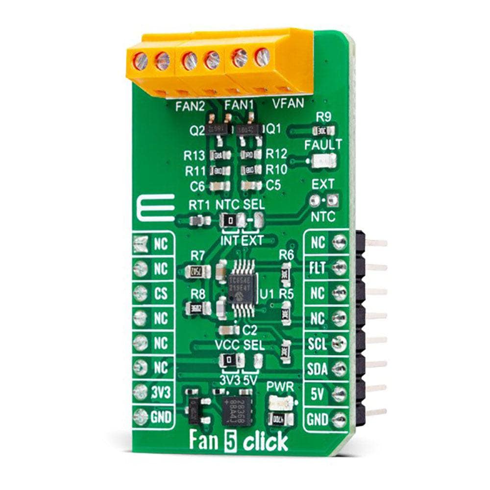
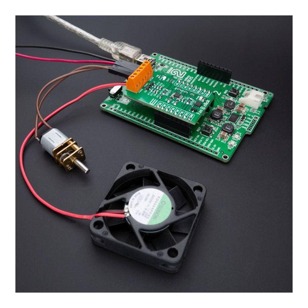
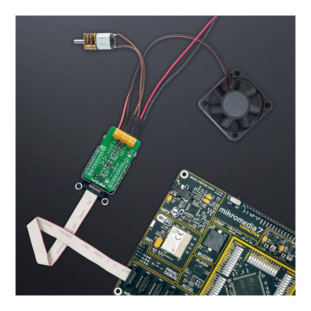
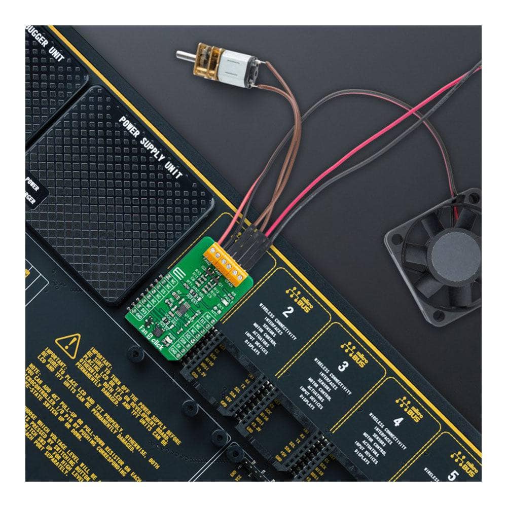
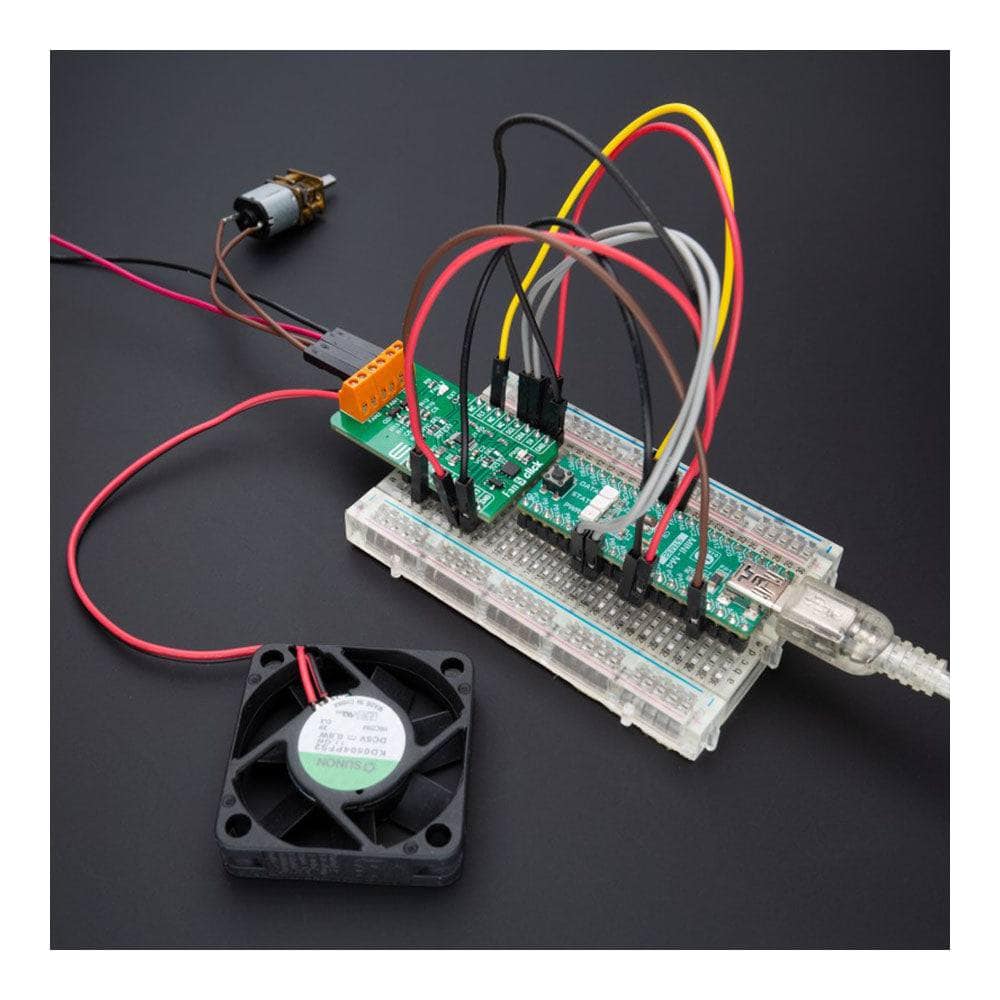
Présentation de la carte Click Board™ Fan 5 - la solution ultime pour gérer la vitesse de votre ventilateur ! Cette carte complémentaire compacte est dotée du TC654 de Microchip, un contrôleur de vitesse de ventilateur en mode PWM avec technologie FanSense™, ce qui la rend parfaite pour les ventilateurs CC sans balais. Grâce à son contrôle de vitesse de ventilateur proportionnel à la température, vous bénéficierez d'un bruit acoustique plus faible et d'une longévité accrue du ventilateur. De plus, avec la possibilité de contrôler la vitesse de deux ventilateurs de refroidissement en fonction de la température de la thermistance ou du cycle de service PWM programmé en I2C, et un indicateur de panne de ventilateur pour vous avertir lorsque le régime du ventilateur tombe en dessous d'un seuil défini par l'utilisateur, cette carte Click™ est idéale pour les équipements réseau, les serveurs et d'autres applications nécessitant un refroidissement et un contrôle de la température.
Et le meilleur dans tout ça ? Le Fan 5 Click Board™ est pris en charge par une bibliothèque compatible mikroSDK qui simplifie le développement logiciel et est livrée entièrement testée et prête à être utilisée avec un système équipé du socket microBUS™. Ne vous contentez pas de moins : passez dès aujourd'hui au Fan 5 Click Board™ !
How Does The Fan 5 Click Board™Work?
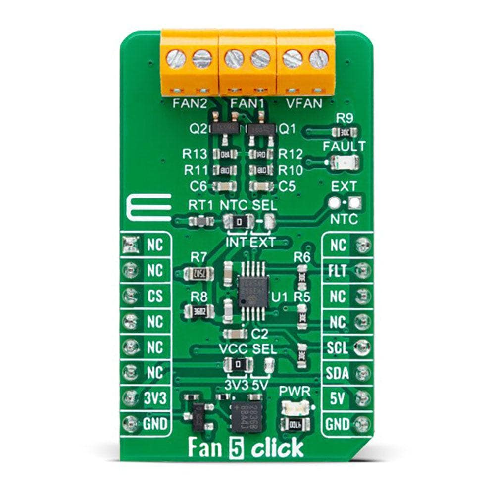
The Fan 5 Click Board™ is based on the TC654, a fan speed controller from Microchip that allows you to control and monitor the speed of two DC brushless fans. The TC654 is based on the FanSense™ technology, which protects your application against fan failure and eliminates the need for 3-wire fans. With the TC654, the fan speed can be controlled by its input voltage or the serial interface, allowing for high flexibility. The input voltage of the TC654 represents temperature, typically provided by a chosen internal or external thermistor (selected through an NTC SEL jumper). The TC654 controls fan speed according to the system temperature by pulse-width modulating the voltage across the fan. This method reduces the fan's acoustic noise and extends the fan's working life.
An external N-channel MOSFET, one per channel, controls the fans. Modulating the voltage applied to the gate of the MOSFETs also modulates the voltage applied to the fan. The PWM output can be adjusted between 30% and 100%, based on the TC654's input voltage, or programmed, as mentioned, via the I2C interface to allow fan speed control without needing an external thermistor. The standard I2C 2-Wire interface reads data and configures settings with a maximum frequency of 100kHz.
The TC654 also measures and monitors fan revolutions per minute (RPM), representing a measure of its health. As a fan's bearings wear out, the fan slows down and eventually stops (locked rotor). The TC654 can detect open, shorted, unconnected, and locked rotor fan conditions by monitoring the fan's RPM level. Apart from the availability of this information on the FLT pin of the mikroBUS™ socket, this condition can also be visually detected through the red LED marked with FAULT. The fan RPM data and threshold registers are available over the I2C interface, allowing complete system control.
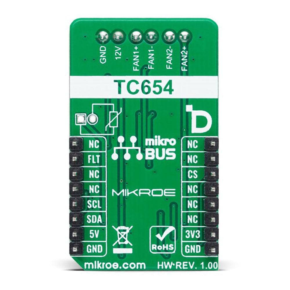
In addition to the two terminals for fan connections, there is another terminal, VFAN, for an external 12V power supply for FAN1. FAN2 uses the necessary supply from the 5V mikroBUS™ power rail.
The Fan 5 Click Board™ can operate with both 3.3V and 5V logic voltage levels selected via the VCC SEL jumper. This way, it is allowed for both 3.3V and 5V capable MCUs to use the communication lines properly. However, the Click board™ comes equipped with a library containing easy-to-use functions and an example code that can be used, as a reference, for further development.
SPECIFICATIONS
Type | Brushless |
Applications | Can be used for networking equipment, servers, or other applications requiring cooling and temperature control |
On-board modules | TC654 - fan speed controller from Microchip |
Key Features | Temperature proportional fan speed, reduced noise, 5V and 12V fan drive, FanSense™ technology protecting against fan failure, PWM fan drive, I2C interface, selectable thermistor, fault LED indicator, and more |
Interface | I2C |
Compatibility | mikroBUS |
Click board size | M (42.9 x 25.4 mm) |
Input Voltage | 3.3V or 5V |
PINOUT DIAGRAM
This table shows how the pinout of the Fan 5 Click Board™ corresponds to the pinout on the mikroBUS™ socket (the latter shown in the two middle columns).
Notes | Pin | Pin | Notes | ||||
---|---|---|---|---|---|---|---|
NC | 1 | AN | PWM | 16 | NC | ||
NC | 2 | RST | INT | 15 | FLT | Fault Indicator | |
NC | 3 | CS | RX | 14 | NC | ||
NC | 4 | SCK | TX | 13 | NC | ||
NC | 5 | MISO | SCL | 12 | SCL | I2C Clock | |
NC | 6 | MOSI | SDA | 11 | SDA | I2C Data | |
Power Supply | 3.3V | 7 | 3.3V | 5V | 10 | 5V | Power Supply |
Ground | GND | 8 | GND | GND | 9 | GND | Ground |
ONBOARD SETTINGS AND INDICATORS
Label | Name | Default | Description |
---|---|---|---|
LD1 | PWR | - | Power LED Indicator |
LD2 | FAULT | - | Fault LED Indicator |
JP1 | VCC SEL | Left | Logic Level Voltage Selection 3V3/5V: Left position 3V3, Right position 5V |
JP2 | NTC SEL | Left | NTC Thermistor Selection INT/EXT: Left position INT, Right position EXT |
J1 | EXT NTC | Unpopulated | External NTC Thermistor Connection Header |
FAN 5 CLICK ELECTRICAL SPECIFICATIONS
Description | Min | Typ | Max | Unit |
---|---|---|---|---|
Supply Voltage | 3.3 | - | 5 | V |
VFAN Supply Voltage | - | 12 | - | V |
Software Support
Software Support
We provide a library for the Fan 5 Click Board™ as well as a demo application (example), developed using MikroE compilers. The demo can run on all the main MikroE development boards.
The package can be downloaded/installed directly from NECTO Studio The package Manager(recommended), downloaded from our LibStock™ or found on MikroE Github account.
Library Description
This library contains API for the Fan 5 Click Board™ driver.
Key functions
-
fan5_get_rpm1
Fan 5 get speed of FAN1. -
fan5_set_duty_cycle
Fan 5 set duty cycle. -
fan5_turn_on_fans
Fan 5 turn on fans.
Example Description
This example demonstrates the use of the Fan 5 Click Board™ by controlling and regulating the fan motor's speed.
void application_task ( void )
{
#if defined FAN_CONTROL_MODE
uint16_t speed;
uint8_t flag_data;
fan5_get_rpm1( &fan5, &speed);
log_printf( &logger, " SPEED: %d RPM rn", speed );
if ( FAN5_FAULT == fan5_get_fault_state( &fan5 ) )
{
fan5_get_status_flags ( &fan5, &flag_data );
log_printf( &logger, " FLAG: %d rn", flag_data );
if ( FAN5_F1F_FLAG & flag_data )
{
log_printf( &logger, " FAN SPEED DROPED !!! rn" );
log_printf( &logger, " OUTPUT IS DISABLED rn" );
fan5_turn_off_fans( &fan5 );
for( ; ; );
}
}
Delay_ms( 2000 );
#else
uint16_t speed;
uint8_t duty_value;
for ( duty_value = FAN5_30_PER_DUTY; duty_value <= FAN5_100_PER_DUTY; duty_value++ )
{
fan5_set_duty_cycle( &fan5, duty_value );
log_printf( &logger, " Duty value: %d rn", ( uint16_t ) duty_value );
Delay_ms( 5000 );
fan5_get_rpm1( &fan5, &speed);
log_printf( &logger, " SPEED: %d RPM rn", speed );
Delay_ms( 500 );
}
#endif
}
The full application code, and ready to use projects can be installed directly from NECTO Studio The package Manager(recommended), downloaded from our LibStock™ or found on MikroE Github account.
Other MikroE Libraries used in the example:
- MikroSDK.Board
- MikroSDK.Log
- Click.Fan5
Additional Notes and Information
Depending on the development board you are using, you may need USB UART Click Board™, USB UART 2 Click or RS232 Click to connect to your PC, for development systems with no UART to USB interface available on the board. UART terminal is available in all MikroE compilers.
MIKROSDK
The Fan 5 Click Board™ is supported with mikroSDK - MikroE Software Development Kit. To ensure proper operation of mikroSDK compliant Click board™ demo applications, mikroSDK should be downloaded from the LibStock and installed for the compiler you are using.
Software Support
Software Support
We provide a library for the Fan 5 Click Board™ as well as a demo application (example), developed using MikroE compilers. The demo can run on all the main MikroE development boards.
The package can be downloaded/installed directly from NECTO Studio The package Manager(recommended), downloaded from our LibStock™ or found on MikroE Github account.
Library Description
This library contains API for the Fan 5 Click Board™ driver.
Key functions
-
fan5_get_rpm1
Fan 5 get speed of FAN1. -
fan5_set_duty_cycle
Fan 5 set duty cycle. -
fan5_turn_on_fans
Fan 5 turn on fans.
Example Description
This example demonstrates the use of the Fan 5 Click Board™ by controlling and regulating the fan motor's speed.
void application_task ( void )
{
#if defined FAN_CONTROL_MODE
uint16_t speed;
uint8_t flag_data;
fan5_get_rpm1( &fan5, &speed);
log_printf( &logger, " SPEED: %d RPM rn", speed );
if ( FAN5_FAULT == fan5_get_fault_state( &fan5 ) )
{
fan5_get_status_flags ( &fan5, &flag_data );
log_printf( &logger, " FLAG: %d rn", flag_data );
if ( FAN5_F1F_FLAG & flag_data )
{
log_printf( &logger, " FAN SPEED DROPED !!! rn" );
log_printf( &logger, " OUTPUT IS DISABLED rn" );
fan5_turn_off_fans( &fan5 );
for( ; ; );
}
}
Delay_ms( 2000 );
#else
uint16_t speed;
uint8_t duty_value;
for ( duty_value = FAN5_30_PER_DUTY; duty_value <= FAN5_100_PER_DUTY; duty_value++ )
{
fan5_set_duty_cycle( &fan5, duty_value );
log_printf( &logger, " Duty value: %d rn", ( uint16_t ) duty_value );
Delay_ms( 5000 );
fan5_get_rpm1( &fan5, &speed);
log_printf( &logger, " SPEED: %d RPM rn", speed );
Delay_ms( 500 );
}
#endif
}
The full application code, and ready to use projects can be installed directly from NECTO Studio The package Manager(recommended), downloaded from our LibStock™ or found on MikroE Github account.
Other MikroE Libraries used in the example:
- MikroSDK.Board
- MikroSDK.Log
- Click.Fan5
Additional Notes and Information
Depending on the development board you are using, you may need USB UART Click Board™, USB UART 2 Click or RS232 Click to connect to your PC, for development systems with no UART to USB interface available on the board. UART terminal is available in all MikroE compilers.
MIKROSDK
The Fan 5 Click Board™ is supported with mikroSDK - MikroE Software Development Kit. To ensure proper operation of mikroSDK compliant Click board™ demo applications, mikroSDK should be downloaded from the LibStock and installed for the compiler you are using.
Frequently Asked Questions
Ask a Question-
Is the Mikroe Fan 5 Click Board™ compatible with other mikroBUS™ boards?
Yes, the Mikroe Fan 5 Click Board™ is compatible with any development board that has a mikroBUS™ socket.
-
Does the Mikroe Fan 5 Click Board™ have an automatic speed control?
No, the Mikroe Fan 5 Click Board™ doesn’t have an automatic speed control feature. It requires a microcontroller to send PWM signals to control the fan speed.
-
What is the voltage and current rating of the Mikroe Fan 5 Click Board™?
The Mikroe Fan 5 Click Board™ can handle a supply voltage of 5V and a maximum current of 2A. Fans rated at 12V and 5V are compatible.
-
What is the maximum fan speed that can be controlled with the Mikroe Fan 5 Click Board™?
The maximum fan speed that can be controlled with the Mikroe Fan 5 Click Board™ is dependent on the fan that is being used. The board can generate PWM signals with a frequency of 25 kHz, and the duty cycle of the signals can be adjusted to control the speed of the fan.
-
How do I use the Mikroe Fan 5 Click Board™?
The Mikroe Fan 5 Click Board™ can be used with a variety of microcontroller boards, such as the MikroElektronika Flip & Click, Arduino, and Raspberry Pi. To use the board, you will need to connect it to your microcontroller board using the mikroBUS™ socket, and then use the appropriate programming language and library to send PWM signals to the board to control the speed of the fan.
-
What is the Mikroe Fan 5 Click Board™?
The Mikroe Fan 5 Click Board™ is a fan speed controller that allows you to control the speed of a DC fan using PWM (Pulse Width Modulation) signals. It can be used to control the speed of fans in a variety of applications, such as cooling systems, ventilation systems, and more.