


Mikroelektronika d.o.o.
Tableau de clic Flash 10
Tableau de clic Flash 10
SKU: MIKROE-5289
Impossible de charger la disponibilité du service de retrait
Key Features
Overview
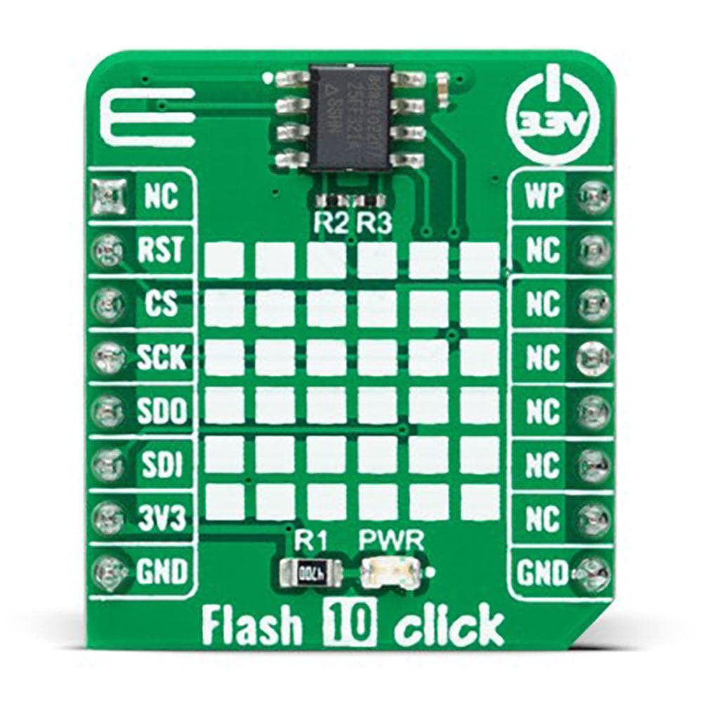
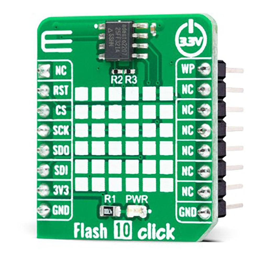
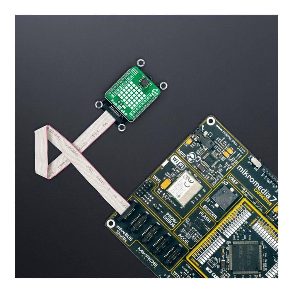
The Flash 10 Click Board™ is a compact add-on board representing a highly reliable memory solution. This board features the AT25FF321A, an SPI configurable 32Mbit (2Mx16) serial Flash memory solution from Dialog Semiconductor. The AT25FF321A is an ideal solution for systems in which program code is shadowed from Flash memory into embedded or external RAM (code shadow) for execution and where small amounts of data are stored and updated locally in the Flash memory. It has a flexible and optimized erase architecture for code and data storage applications, non-volatile protection, and four specialized 128-byte OTP security registers to store a unique device ID and locked key storage. This memory can withstand many write cycles (minimum 100k) and has a data retention period greater than 20 years. This Click board™ is suitable for storage and data transfer in consumer devices, enterprise systems, and industrial applications.
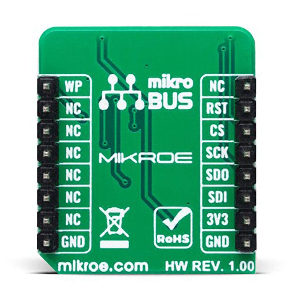
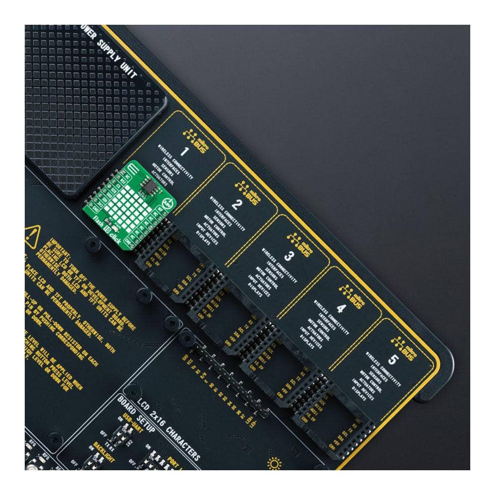
The Flash 10 Click Board™ is supported by a mikroSDK compliant library, which includes functions that simplify software development. This Click board™ comes as a fully tested product, ready to be used on a system equipped with the mikroBUS™ socket.
Downloads
La carte Flash 10 Click Board™ est une carte complémentaire compacte qui représente une solution de mémoire extrêmement fiable. Cette carte comprend l'AT25FF321A, une solution de mémoire Flash série 32 Mbit (2Mx16) configurable SPI de Dialog Semiconductor. L'AT25FF321A est une solution idéale pour les systèmes dans lesquels le code du programme est copié de la mémoire Flash vers la RAM intégrée ou externe (code shadow) pour l'exécution et où de petites quantités de données sont stockées et mises à jour localement dans la mémoire Flash. Elle dispose d'une architecture d'effacement flexible et optimisée pour les applications de stockage de code et de données, d'une protection non volatile et de quatre registres de sécurité OTP spécialisés de 128 octets pour stocker un identifiant d'appareil unique et un stockage de clé verrouillée. Cette mémoire peut supporter de nombreux cycles d'écriture (minimum 100 000) et a une période de conservation des données supérieure à 20 ans. Cette carte Click board™ convient au stockage et au transfert de données dans les appareils grand public, les systèmes d'entreprise et les applications industrielles.
La carte Flash 10 Click Board™ est supportée par une bibliothèque compatible mikroSDK, qui comprend des fonctions qui simplifient le développement logiciel. Cette carte Click Board™ est un produit entièrement testé, prêt à être utilisé sur un système équipé du socket mikroBUS™.
| General Information | |
|---|---|
Part Number (SKU) |
MIKROE-5289
|
Manufacturer |
|
| Physical and Mechanical | |
Weight |
0.02 kg
|
| Other | |
EAN |
8606027387920
|
Frequently Asked Questions
Have a Question?
Be the first to ask a question about this.