


Mikroelektronika d.o.o.
Tableau de clic LightRanger 9
Tableau de clic LightRanger 9
Impossible de charger la disponibilité du service de retrait
Key Features:
- Technologie ToF directe avec détection SPAD haute sensibilité, configuration multizone configurable 8x8 avec détection multi-objets, champ de vision réglable, filtre et algorithme de rejet de la lumière solaire sur puce hautes performances, lentille de protection intégrée, et plus encore
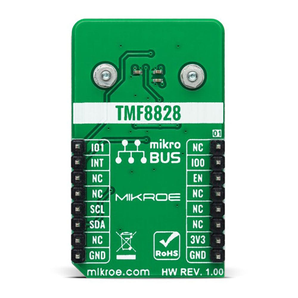
- Basé sur le capteur TMF8828 - Multizone Time-of-Flight d'AMS AG
- Peut être utilisé pour la détection de présence (objet), la mesure de distance, la télémétrie industrielle, le contrôle des stocks, etc.
- mikroBUS : interface I2C
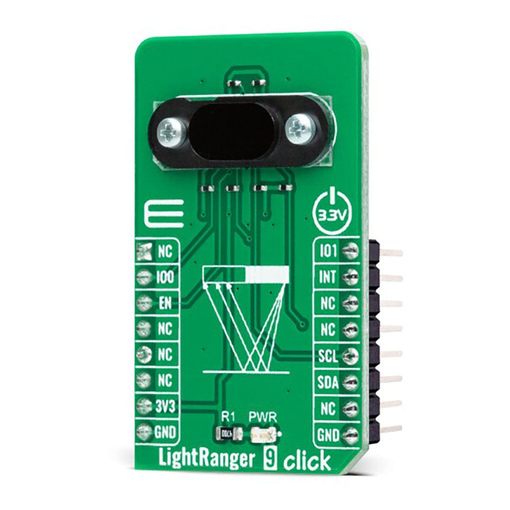
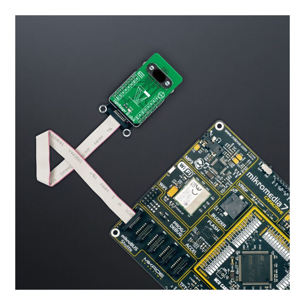
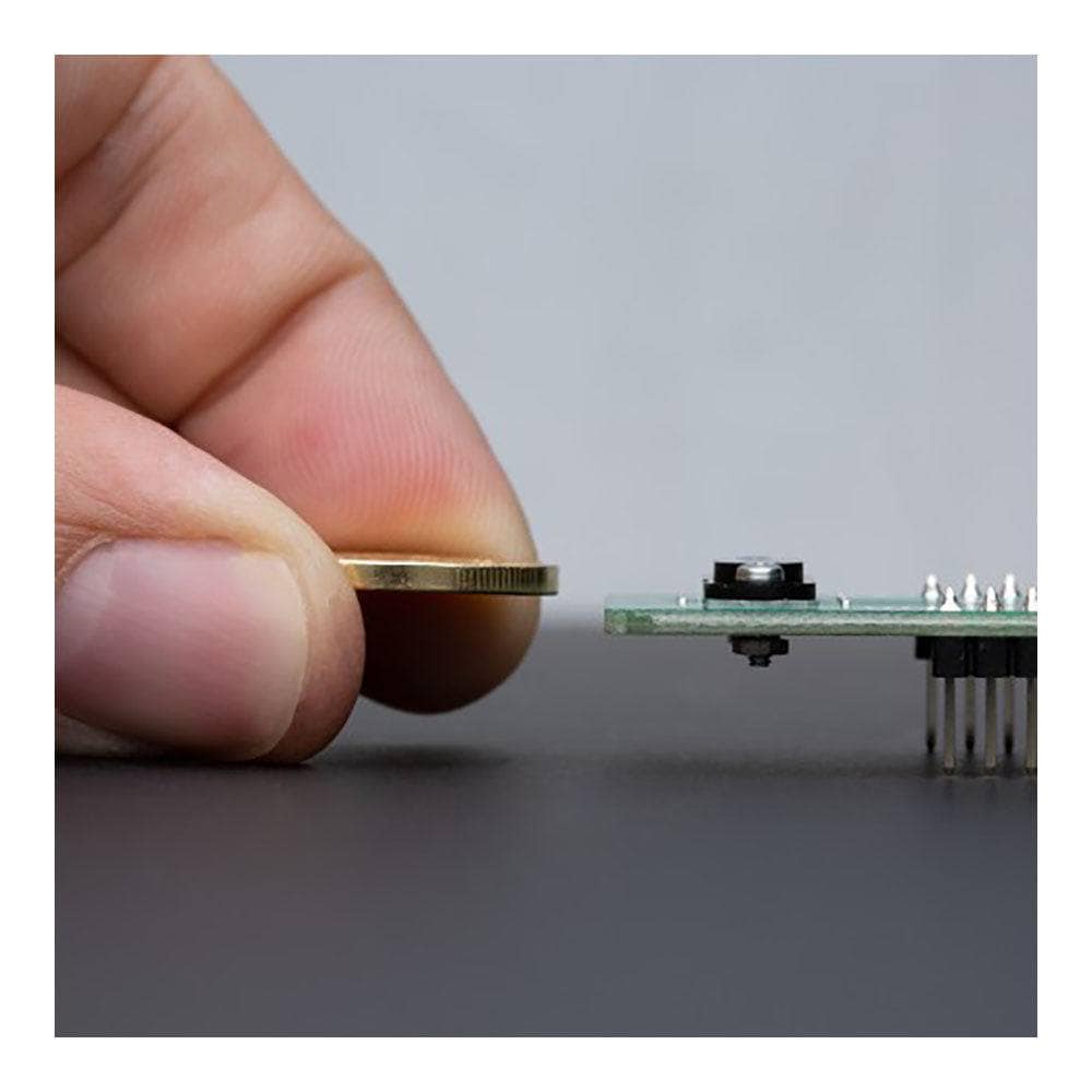
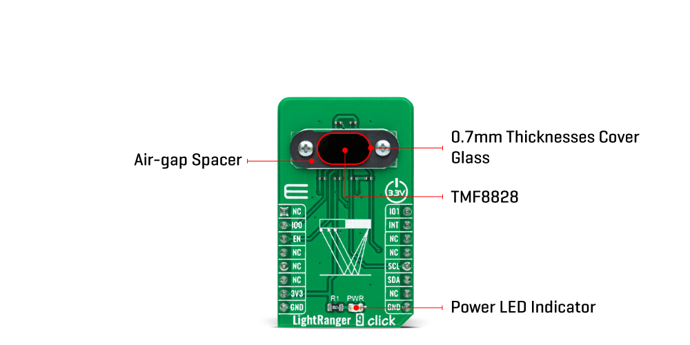
La carte Click Board™ LightRanger 9 est une carte complémentaire compacte adaptée aux applications de télémétrie et de détection de distance. Cette carte comprend le TMF8828, un capteur de distance optique dToF (temps de vol direct) avec un laser à cavité verticale à émission par la surface (VCSEL) intégré permettant de détecter une cible jusqu'à 5 m de distance depuis AMS AG. Grâce à sa lentille sur le SPAD, il prend en charge les données de sortie multizones 3x3, 4x4, 3x6 et 8x8 et un champ de vision large et réglable de manière dynamique. Tout le traitement des données brutes est effectué à l'intérieur du TMF8828, fournissant des informations de distance et des valeurs de confiance via son interface I2C. Un ajout unique à cette carte Click™ représente une lentille de protection supplémentaire de 0,7 mm d'épaisseur qui réduit encore davantage les interférences et améliore la précision du capteur. Cette carte Click™ convient à la détection de présence (objet), à la mesure de distance, à la télémétrie industrielle, au contrôle des stocks et à de nombreuses autres applications.
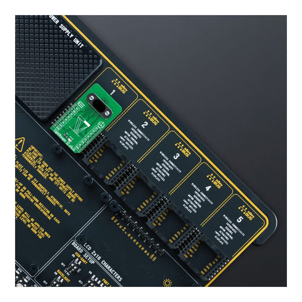
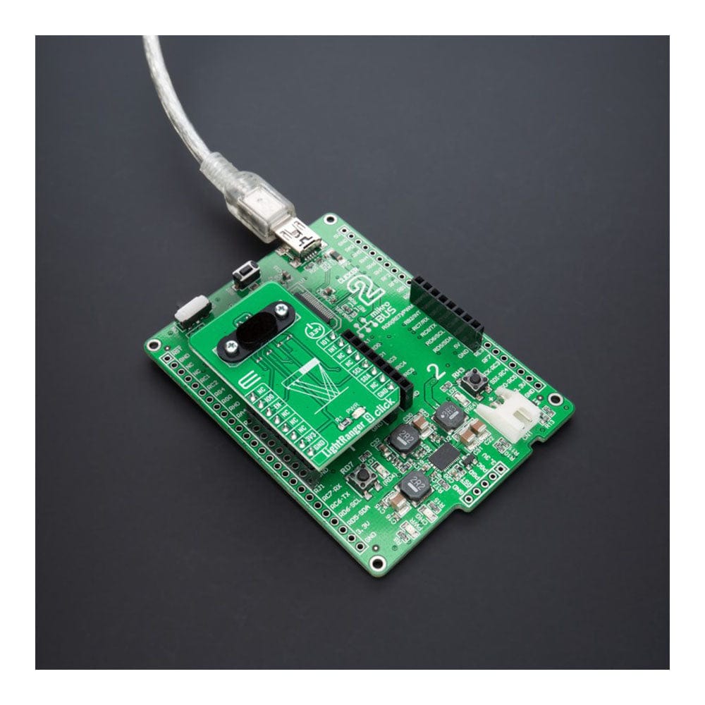
La carte Click Board™ LightRanger 9 est prise en charge par une bibliothèque compatible mikroSDK, qui comprend des fonctions qui simplifient le développement logiciel. Cette carte Click Board™ est un produit entièrement testé, prêt à être utilisé sur un système équipé du socket mikroBUS™.
How Does The LightRanger 9 Click Board™ Work?
The LightRanger 9 Click Board™ is based on the the TMF8801, a dToF wide field of view optical distance sensor module with multizone from ams AG. This sensor is built using a single-photon avalanche diode (SPAD) array, time-to-digital converter (TDC), and histogram technology featuring an associated VCSEL, while the high-quality lens on the SPAD supports a dynamically adjustable field of view up to 63°. The TMF8828 detects the target area in multiple zones with precise measurement results, with a minimum distance of 10mm and a maximum of 5m. It can also detect numerous objects per zone, allowing automated robots to gain additional sensory awareness and provide early alerts to potential obstacles.
The TMF8828 operating principle uses a pulse train of VCSEL pulses defined by the iteration setting. These pulses are spread using an MLA (microlens array) to illuminate the FoI (illumination field). An object reflects these rays to the TMF8828 receiver optics lens and onto an array of SPAD (single-photon avalanche detector). A TDC (time to digital converter) measures the time from the emission of these pulses to their arrival and accumulates the hits into bins inside a histogram. As mentioned before, the TMF8828 comes with a multizone operation.
It has two operating modes, a mode with 3x3, 4x4, or 3x6 zones, or 8x8 zones, which implements its functionality as a sequence of four time-multiplexed measurements of 4x4 zones. As such, the factory calibration sequence, loading the calibration data, reading the result measurements, and the optional histogram readouts must be performed four times in series by the host. Also, unique addition to this Click board™ represents an additional 0.7mm thick protective lens, alongside a 0.38mm air-gap spacer that separates the lens from the sensor, further reducing interference and improving the sensor's accuracy.
The LightRanger 9 Click Board™ communicates with MCU using the standard I2C 2-Wire interface supporting Fast Mode operation with a clock frequency of 1MHz. It provides distance information together with confidence values through its serial interface. The internal processor of the TMF8828 (ARM M0+®) executes the AMS algorithm on these histograms, to calculate the target distance of the object presented in mm through the I2C interface for each of the zones.
Also, it provides the possibility of the device Power-Up feature (Enable) routed to the CS pin of the mikroBUS™ socket, interrupt feature on the INT pin of the mikroBUS™ to optimize ranging operation, and two pins on the RST and PWM pins of the mikroBUS™ socket used as general-purpose I/O signals.
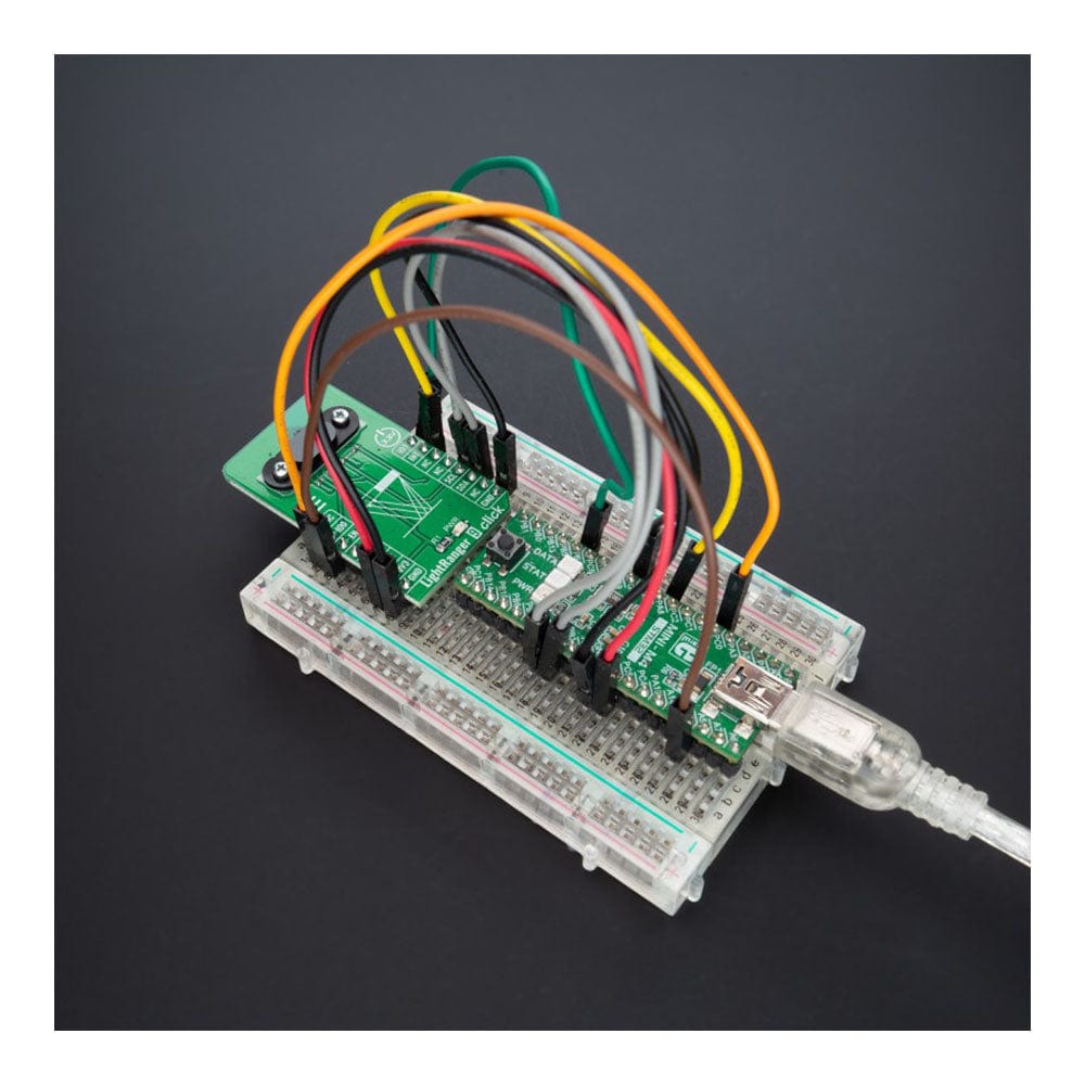
The LightRanger 9 Click Board™ can be operated only with a 3.3V logic voltage level. The board must perform appropriate logic voltage level conversion before using MCUs with different logic levels. However, the Click board™ comes equipped with a library containing functions and an example code that can be used, as a reference, for further development.
SPECIFICATIONS
| Type | Optical |
| Applications | Can be used for presence (object) detection, distance measurement, industrial ranging, inventory control, and more |
| On-board modules | TMF8801 - Multizone Time-of-Flight sensor from ams AG |
| Key Features | Direct ToF technology with high sensitivity SPAD detection, 8x8 configurable multi-zone configuration with multi-object detection, adjustable field of view, high performance on-chip sunlight rejection filter and algorithm, onboard protective lens, and more |
| Interface | I2C |
| Compatibility | mikroBUS |
| Click board size | M (42.9 x 25.4 mm) |
| Input Voltage | 3.3V |
PINOUT DIAGRAM
This table shows how the pinout on the LightRanger 9 Click Board™ corresponds to the pinout on the mikroBUS™ socket (the latter shown in the two middle columns).
| Notes | Pin | Pin | Notes | ||||
|---|---|---|---|---|---|---|---|
| NC | 1 | AN | PWM | 16 | IO1 | General Purpse I/O | |
| General Purpse I/O | IO0 | 2 | RST | INT | 15 | INT | Interrupt |
| Enable | EN | 3 | CS | RX | 14 | NC | |
| NC | 4 | SCK | TX | 13 | NC | ||
| NC | 5 | MISO | SCL | 12 | SCL | I2C Clock | |
| NC | 6 | MOSI | SDA | 11 | SDA | I2C Data | |
| Power Supply | 3.3V | 7 | 3.3V | 5V | 10 | NC | |
| Ground | GND | 8 | GND | GND | 9 | GND | Ground |
ONBOARD SETTINGS AND INDICATORS
| Label | Name | Default | Description |
|---|---|---|---|
| LD1 | PWR | - | Power LED Indicator |
LIGHTRANGER 9 CLICK ELECTRICAL SPECIFICATIONS
| Description | Min | Typ | Max | Unit |
|---|---|---|---|---|
| Supply Voltage | - | 3.3 | - | V |
| Distance Measurement Range | 10 | - | 5000 | mm |
| Field of View | - | - | 63 | Deg |
| VCSEL Wavelength | - | 940 | - | nm |
| Operating Temperature Range | -30 | +25 | +70 | °C |
Software Support
We provide a library for the LightRanger 9 Click Board™ as well as a demo application (example), developed using MikroElektronika compilers. The demo can run on all the main MikroElektronika development boards.
The package can be downloaded/installed directly from NECTO Studio The package Manager (recommended), downloaded from our LibStock™ or found on MikroE Github account.
Library Description
This library contains API for the LightRanger 9 Click Board™ driver.
Key functions
-
lightranger9_get_int_pinThis function returns the INT pin logic state. -
lightranger9_clear_interruptsThis function reads and clears the interrupt status register. -
lightranger9_get_captureThis function reads and parses a single sub-capture block of 132 bytes.
Example Description
This example demonstrates the use of the LightRanger 9 Click Board™ by reading and displaying all four sub-captures data measurements on the USB UART.
void application_task ( void )
 {
     while ( lightranger9_get_int_pin ( &lightranger9 ) );

     lightranger9_capture_t capture;
     if ( ( LIGHTRANGER9_OK == lightranger9_clear_interrupts ( &lightranger9 ) ) &&
          ( LIGHTRANGER9_OK == lightranger9_get_capture ( &lightranger9, &capture ) ) )
     {
         lightranger9_log_results ( capture );
     }
 }
The full application code, and ready to use projects can be installed directly from NECTO Studio The package Manager (recommended), downloaded from our LibStock™ or found on MikroE Github account.
Other MikroE Libraries used in the example:
- MikroSDK.Board
- MikroSDK.Log
- Click.LightRanger9
Additional Notes and Information
Depending on the development board you are using, you may need USB UART Click Board™, USB UART 2 Click or RS232 Click to connect to your PC, for development systems with no UART to USB interface available on the board. UART terminal is available in all MikroElektronika compilers.
MIKROSDK
The is supported with mikroSDK - MikroElektronika Software Development Kit. To ensure proper operation of mikroSDK compliant Click board™ demo applications, mikroSDK should be downloaded from the LibStock and installed for the compiler you are using.
Tableau de clic LightRanger 9
Frequently Asked Questions
Have a Question?
Be the first to ask a question about this.