


Mikroelektronika d.o.o.
Carte à clic NFC Tag 5
Carte à clic NFC Tag 5
SKU: MIKROE-5230
Impossible de charger la disponibilité du service de retrait


Key Features
Overview
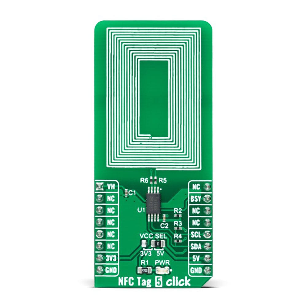
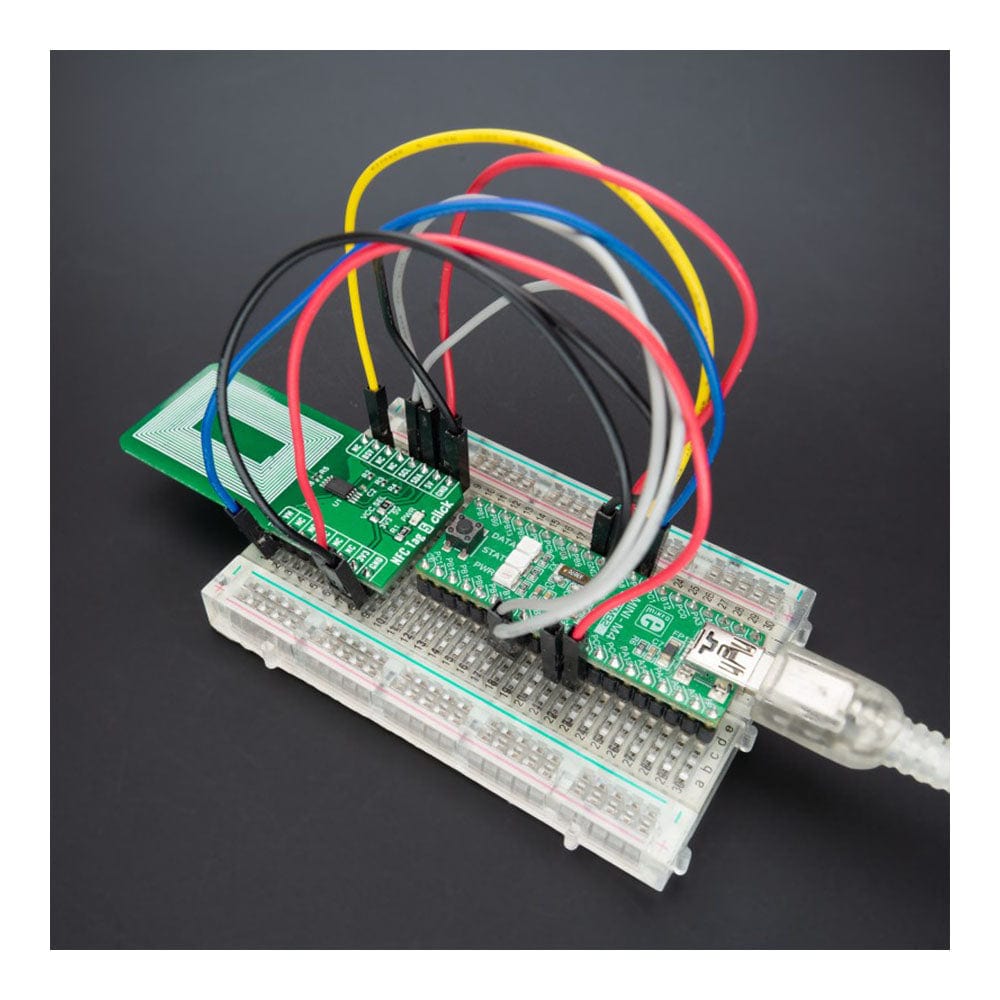
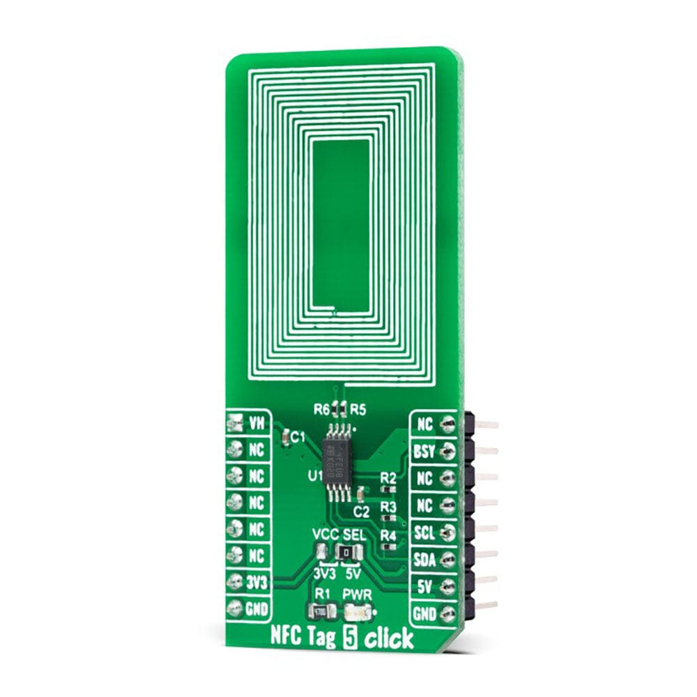
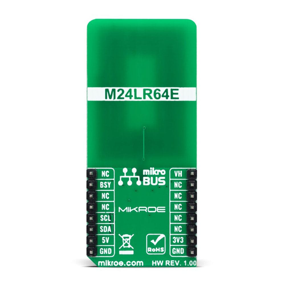
The NFC Tag 5 Click Board™ is a compact add-on board that contains a compact NFC tag IC. This board features the M24LR64E-R, a dynamic NFC/RFID tag IC with a dual interface 64-Kbit EEPROM from STMicroelectronics. It features an I2C interface alongside an RF contactless interface operating at 13.56MHz, organized as 8192×8 bits in the I2C mode and 2048×32 bits in the ISO 15693 and ISO 18000-3 mode 1 RF mode. The M24LR64E-R also features an energy harvesting analogue output and a user-configurable digital output pin, used as an interrupt, toggling during either RF write in progress or RF busy mode. This Click board™ represents an ideal solution for rapidly integrating NFC tag technology in any custom application such as industrial or medical equipment, consumer electronics, and more.
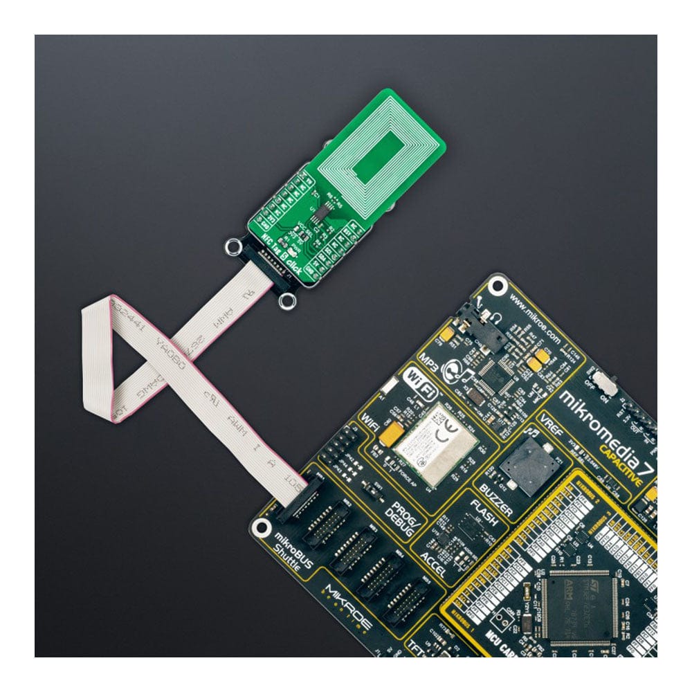
The NFC Tag 5 Click Board™ is supported by a mikroSDK compliant library, including functions that simplify software development. This Click board™ comes as a thoroughly tested product, ready to be used on a system equipped with the mikroBUS™ socket.
Downloads
La carte NFC Tag 5 Click Board™ est une carte complémentaire compacte qui contient un circuit intégré d'étiquette NFC compact. Cette carte comprend le M24LR64E-R, un circuit intégré d'étiquette NFC/RFID dynamique avec une EEPROM 64 Kbit à double interface de STMicroelectronics. Il comprend une interface I2C ainsi qu'une interface sans contact RF fonctionnant à 13,56 MHz, organisée en 8192 × 8 bits en mode I2C et 2048 × 32 bits en mode RF ISO 15693 et ISO 18000-3 mode 1. Le M24LR64E-R dispose également d'une sortie analogique de récupération d'énergie et d'une broche de sortie numérique configurable par l'utilisateur, utilisée comme interruption, basculant pendant l'écriture RF en cours ou le mode RF occupé. Cette carte Click board™ représente une solution idéale pour intégrer rapidement la technologie d'étiquette NFC dans toute application personnalisée telle que les équipements industriels ou médicaux, l'électronique grand public, etc.
La carte NFC Tag 5 Click Board™ est prise en charge par une bibliothèque compatible mikroSDK, comprenant des fonctions qui simplifient le développement logiciel. Cette carte Click Board™ est un produit entièrement testé, prêt à être utilisé sur un système équipé de la prise mikroBUS™.
| General Information | |
|---|---|
Part Number (SKU) |
MIKROE-5230
|
Manufacturer |
|
| Physical and Mechanical | |
Weight |
0.02 kg
|
| Other | |
EAN |
8606027388262
|
Frequently Asked Questions
Have a Question?
Be the first to ask a question about this.