


Mikroelektronika d.o.o.
Tableau magnétique rotatif à 4 clics
Tableau magnétique rotatif à 4 clics
Impossible de charger la disponibilité du service de retrait
Key Features:
- Bonne résolution pour le contrôle du moteur et de la position, interfaces de sortie indépendantes, autodiagnostic, immunité aux champs parasites externes, faible consommation d'énergie, fiabilité et durabilité maximales, support d'aimant rotatif, etc.
- Basé sur l'AS5047D - capteur de position rotatif pour une mesure d'angle absolue rapide sur une plage complète de 360 degrés d'AMS AG
- Peut être utilisé pour prendre en charge la commutation du moteur BLDC pour les applications automobiles les plus difficiles
- mikroBUS : interface SPI
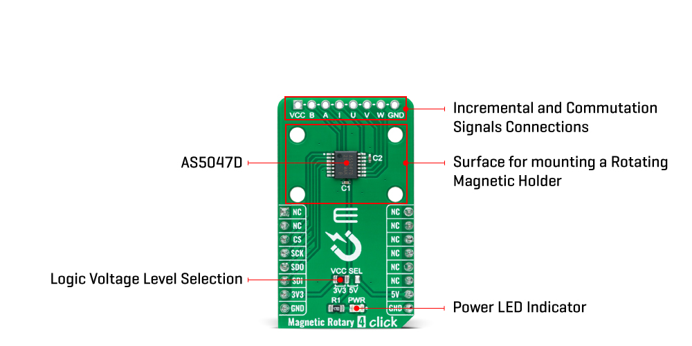
La carte magnétique rotative 4 Click Board™ est une carte complémentaire compacte pour une détection précise de la position de l'aimant. Cette carte comprend l'AS5047D, un capteur de position rotatif haute résolution configurable par SPI pour une mesure d'angle absolue rapide sur une plage complète de 360 degrés d'AMS AG. L'AS5047D est équipé d'une compensation d'erreur d'angle dynamique intégrée révolutionnaire (DAEC™) avec une latence presque nulle et offre une conception robuste qui supprime l'influence de tout champ magnétique parasite externe homogène. Il est également livré avec un en-tête intégré réservé aux signaux incrémentiels et de commutation de leurs signaux A/B/I et U/V/W respectifs ainsi que des autodiagnostics intégrés, y compris l'intensité du champ magnétique, l'aimant perdu et d'autres fonctions de diagnostic associées. Cette carte Click™ a été conçue pour prendre en charge la commutation du moteur BLDC pour les applications automobiles les plus difficiles.
Le Magnetic Rotary 4 Click Board™ est pris en charge par une bibliothèque compatible mikroSDK, qui comprend des fonctions qui simplifient le développement logiciel. Ce Click board™ est un produit entièrement testé, prêt à être utilisé sur un système équipé du socket mikroBUS™.


How Does The Magnetic Rotary 4 Click Board™ Work?
The Magnetic Rotary 4 Click Board™ as its foundation uses the AS5047D, a high-resolution rotary position sensor for fast absolute angle measurement over a full 360-degree range from AMS AG. The core of the AS5047D represents a CMOS technology Hall-effect magnetic sensor that converts the magnetic field component perpendicular to the surface of the chip into a digital value. It allows a host MCU to read 14-bit absolute angle position data from the AS5047D and to program non-volatile settings without a dedicated programmer. It is also equipped with a Dynamic Angle Error Compensation block that corrects the calculated angle regarding latency by using a linear prediction calculation algorithm.
The signals coming from internal Hall sensors are amplified and filtered before their conversion by the ADC and then processed by the CORDIC block to compute the angle and magnitude of the magnetic field vector. The intensity of the magnetic field is used by the automatic gain control (AGC) to adjust the amplification level to compensate for temperature and magnetic field variations.
The Magnetic Rotary 4 Click Board™ communicates with MCU through a standard SPI interface supporting the common SPI mode, SPI Mode 1. This Click board™ also comes with an onboard header reserved for incremental and commutation signals of their respective A/B/I and U/V/W signals alongside embedded self-diagnostics. Incremental movements are indicated on a set of ABI signals with a maximum resolution of 2000 steps / 500 pulses per revolution in decimal mode and 2048 steps / 512 pulses per revolution in binary mode. The resolution of the ABI signal is programmable and can be reduced to 32 or 8 pulses per revolution.
Brushless DC (BLDC) motors are also controllable through a standard UVW commutation interface with a programmable number of pole pairs from 1 to 7. At constant rotation speed, the latency time is internally compensated by the AS5047D, reducing the dynamic angle error at the SPI, ABI, and UVW outputs, while at higher speeds, the interpolator fills in the missing ABI pulses and generates the UVW signals with no loss of resolution. The AS5047D allows selection between a UVW output interface and a PWM-encoded interface on the W pin, which can be seen as an absolute angle position.
Also, unique addition to this board is a position for a rotary magnet holder designed to be used alongside a magnetic rotary position sensor allowing fast prototyping and quick measurements during development.
The Magnetic Rotary 4 Click Board™ can be operated only with a 3.3V logic voltage level. The board must perform appropriate logic voltage level conversion before using MCUs with different logic levels. However, the Click board™ comes equipped with a library containing functions and an example code that can be used, as a reference, for further development.
SPECIFICATIONS
| Type | Magnetic |
| Applications | Can be used to support BLDC motor commutation for the most challenging automotive applications |
| On-board modules | AS5047D - rotary position sensor for fast absolute angle measurement over a full 360-degree range from ams AG |
| Key Features | Good resolution for motor and position control, independent output interfaces, self-diagnostics, immune to an external stray field, low power consumption, highest reliability and durability, rotary magnet holder, and more |
| Interface | SPI |
| Compatibility | mikroBUS |
| Click board size | M (42.9 x 25.4 mm) |
| Input Voltage | 3.3V or 5V |
PINOUT DIAGRAM
This table shows how the pinout on the Magnetic Rotary 4 Click Board™ corresponds to the pinout on the mikroBUS™ socket (the latter shown in the two middle columns).
| Notes | Pin | Pin | Notes | ||||
|---|---|---|---|---|---|---|---|
| NC | 1 | AN | PWM | 16 | NC | ||
| NC | 2 | RST | INT | 15 | NC | ||
| SPI Chip Select | CS | 3 | CS | RX | 14 | NC | |
| SPI Clock | SCK | 4 | SCK | TX | 13 | NC | |
| SPI Data OUT | SDO | 5 | MISO | SCL | 12 | NC | |
| SPI Data IN | SDI | 6 | MOSI | SDA | 11 | NC | |
| Power Supply | 3.3V | 7 | 3.3V | 5V | 10 | 5V | Power Supply |
| Ground | GND | 8 | GND | GND | 9 | GND | Ground |
ONBOARD SETTINGS AND INDICATORS
| Label | Name | Default | Description |
|---|---|---|---|
| LD1 | PWR | - | Power LED Indicator |
| JP1 | VCC SEL | Left | Logic Level Voltage Selection 3V3/5V: Left position 3V3, Right position 5V |
| J1 | - | Unpopulated | Incremental and Commutation Signals Connection Header |
MAGNETIC ROTARY 4 CLICK ELECTRICAL SPECIFICATIONS
| Description | Min | Typ | Max | Unit |
|---|---|---|---|---|
| Supply Voltage | 3.3 | - | 5 | V |
| Rotation Angle Range | 0 | - | 360 | °C |
| Orthogonal Magnetic Field Strength | 35 | - | 70 | mT |
| Core Resolution | - | 14 | - | bit |
| ABI Resolution | 32 | - | 2048 | SpR |
| Maximum Speed | - | - | 14500 | RPM |
| Operating Temperature Range | -40 | +25 | +120 | °C |
Software Support
We provide a library for the Magnetic Rotary 4 Click Board™ as well as a demo application (example), developed using MikroElektronika compilers. The demo can run on all the main MikroElektronika development boards.
The package can be downloaded/installed directly from NECTO Studio The package Manager (recommended), is downloaded from our LibStock™or found on MikroE Github account.
Library Description
This library contains API for the Magnetic Rotary 4 Click Board™ driver.
Key functions
-
magneticrotary4_set_rotation_directionThis function sets the magnet rotation direction to clockwise or counterclockwise. -
magneticrotary4_calibrate_zero_positionThis function calibrates the sensor to zero Angle position. -
magneticrotary4_get_angleThis function reads the absolute position of raw data and converts it to degrees (Angle).
Example Description
This example demonstrates the use of the Magnetic Rotary 4 Click Board™ by reading and displaying the magnet (potentiometer) angular position in degrees.
voidapplication_task( void )
 {
 float angle;
 if ( MAGNETICROTARY4_OK == magneticrotary4_get_angle ( &magneticrotary4, &angle ) )
 {
 log_printf( &logger, " Angle: %.1f degreesrnn", angle );
 Delay_ms ( 100 );
 }
 }
The full application code and ready-to-use projects can be installed directly from NECTO Studio The package Manager (recommended), is downloaded from ourLibStock™or found on the MikroE Github account.
Other MikroE Libraries used in the example:
- MikroSDK.Board
- MikroSDK.Log
- Click.MagneticRotary4
Additional Notes and Information
Depending on the development board you are using, you may need a USB UART Click Board™, USB UART 2 Click or RS232 Click to connect to your PC, for development systems with no UART to USB interface available on the board. UART terminal is available in all MikroElektronika compilers.
MIKROSDK
The Magnetic Rotary 4 Click Board™ is supported with mikroSDK- MikroElektronika Software Development Kit. To ensure proper operation of mikroSDK compliant Click board™ demo applications, mikroSDK should be downloaded from the Libstock and installed for the compiler you are using.
Tableau magnétique rotatif à 4 clics
Frequently Asked Questions
Have a Question?
Be the first to ask a question about this.