


Mikroelektronika d.o.o.
Planche à clic Angle 7
Planche à clic Angle 7
SKU: MIKROE-5196
Impossible de charger la disponibilité du service de retrait
Key Features
Overview
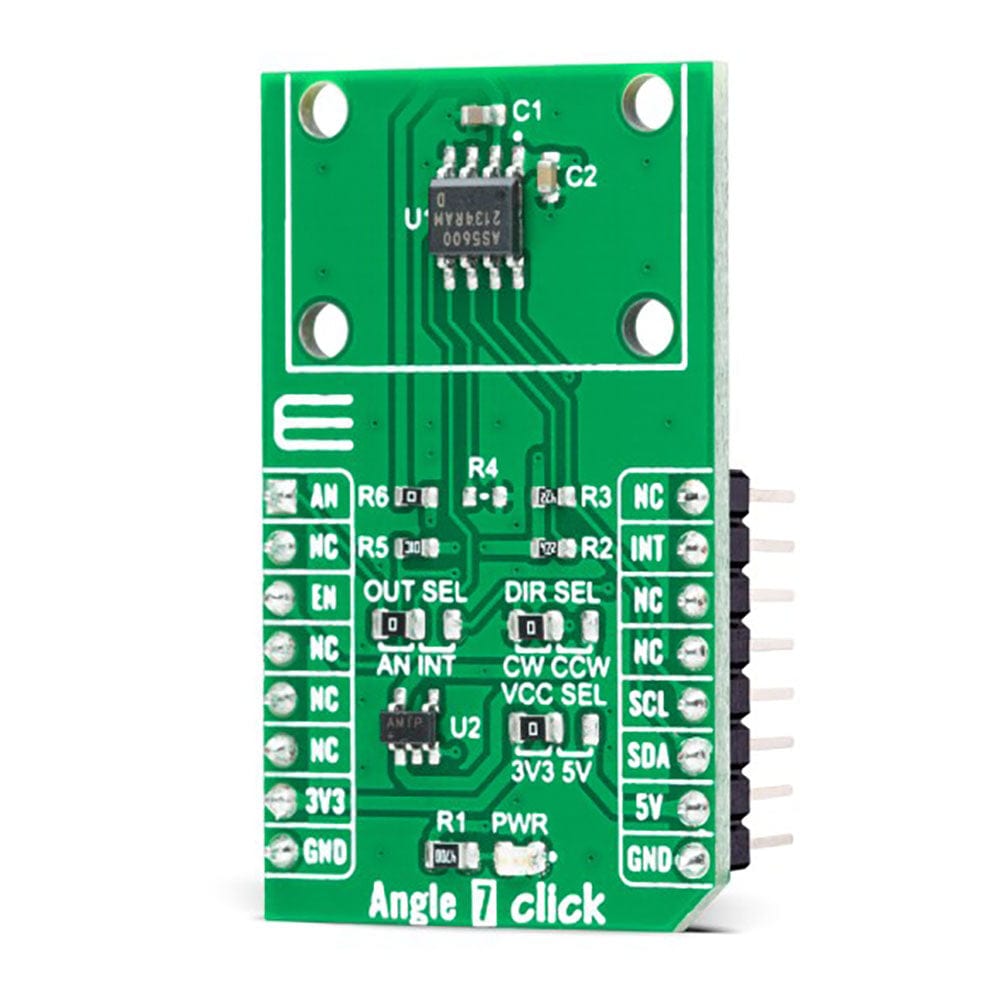
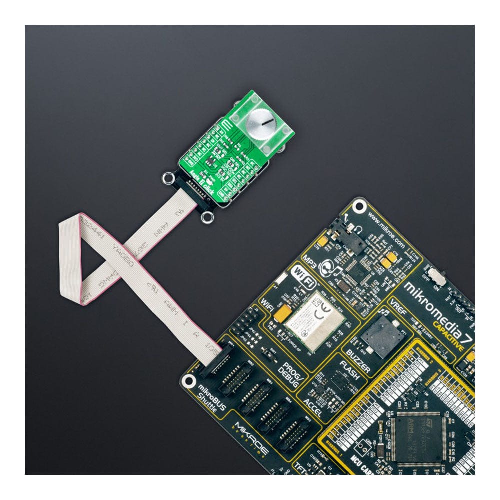
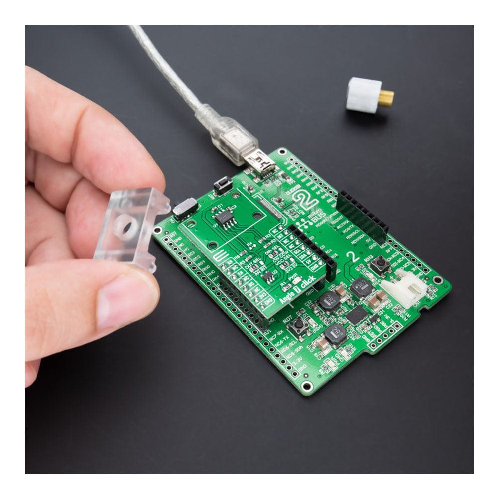
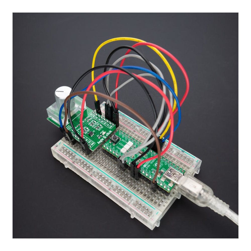
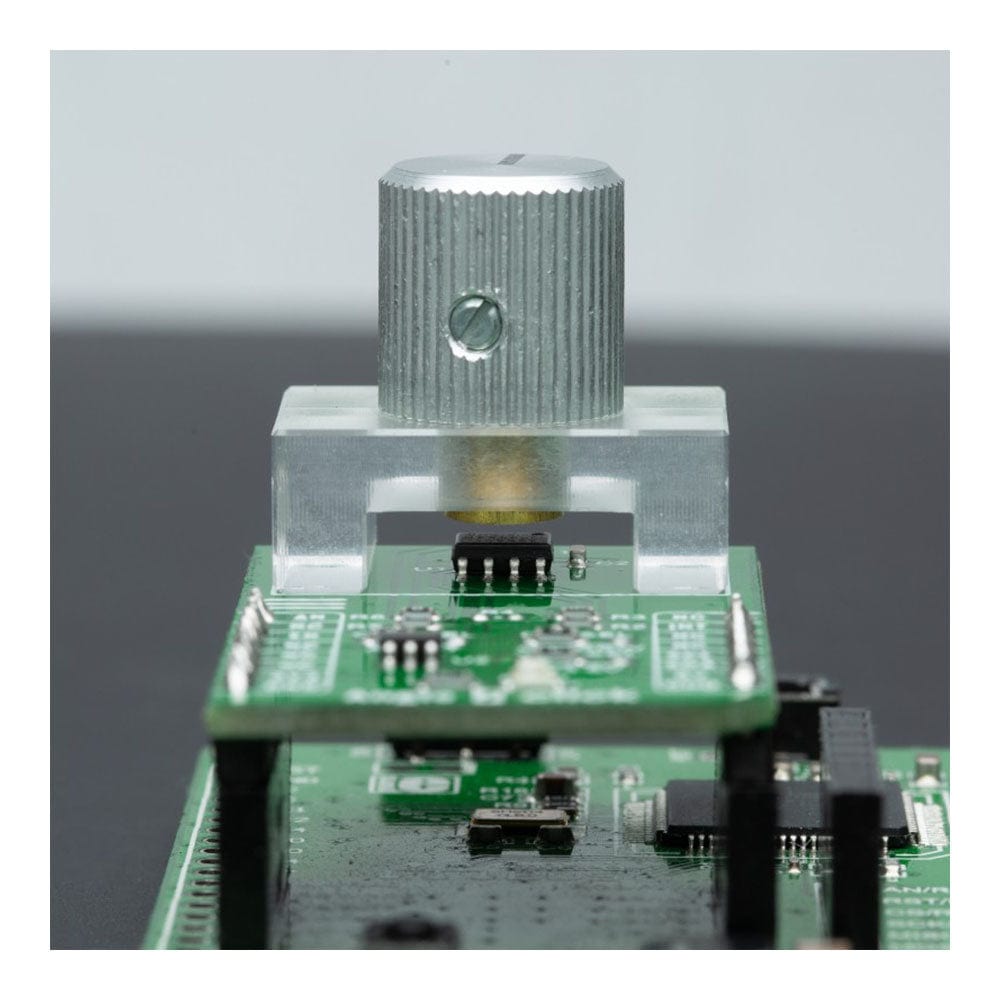
The Angle 7 Click Board™ is a compact add-on board that detects the absolute angular position of a permanent magnet. This board features the AS5600, a programmable Hall-based rotary magnetic position sensor with a high-resolution 12-bit analogue or PWM output from AMS AG. Based on planar Hall technology, this sensor measures the orthogonal component of the flux density (Bz) from an external magnet while rejecting stray magnetic fields. The default range of the output is from 18 to 360 degrees, where the full resolution of the device can be applied to a smaller range by programming a zero angle (start position) and a maximum angle (Stop position) through the I2C interface used for configuration and user programming of non-volatile parameters. This Click board™ is suitable for contactless potentiometers, contactless knobs, RC servos, and other angular position measurement solutions.
The Angle 7 Click Board™ is supported by a mikroSDK compliant library, which includes functions that simplify software development. This Click board™ comes as a fully tested product, ready to be used on a system equipped with the mikroBUS™ socket.
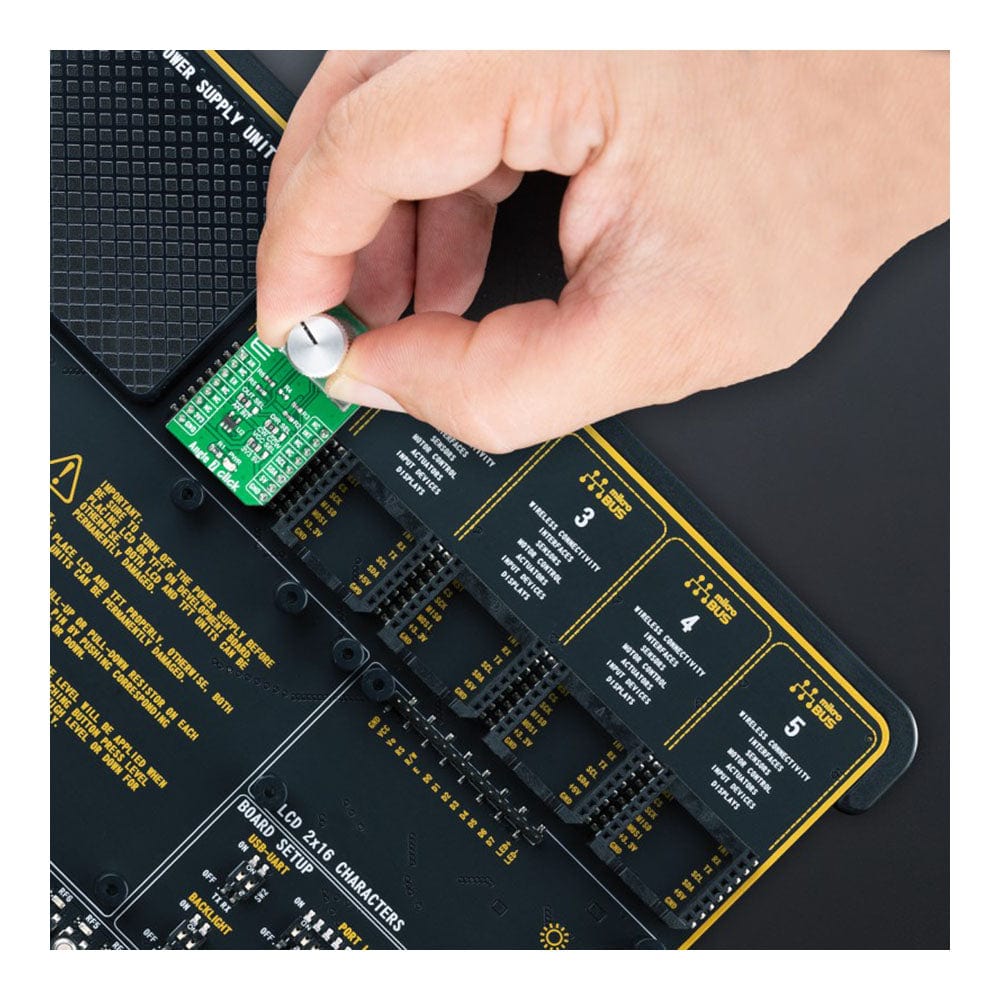
Note: The Click Board does not include the magnet, holder or control knob. This is shown as an example application.
Downloads
La carte Click Board™ Angle 7 est une carte complémentaire compacte qui détecte la position angulaire absolue d'un aimant permanent. Cette carte est équipée de l'AS5600, un capteur de position magnétique rotatif programmable à effet Hall avec une sortie analogique ou PWM 12 bits haute résolution d'AMS AG. Basé sur la technologie Hall planaire, ce capteur mesure la composante orthogonale de la densité de flux (Bz) d'un aimant externe tout en rejetant les champs magnétiques parasites. La plage par défaut de la sortie est de 18 à 360 degrés, où la résolution complète de l'appareil peut être appliquée à une plage plus petite en programmant un angle nul (position de départ) et un angle maximal (position d'arrêt) via l'interface I2C utilisée pour la configuration et la programmation utilisateur des paramètres non volatils. Cette carte Click™ convient aux potentiomètres sans contact, aux boutons sans contact, aux servos RC et à d'autres solutions de mesure de position angulaire.
La carte Click Board™ Angle 7 est prise en charge par une bibliothèque compatible mikroSDK, qui comprend des fonctions qui simplifient le développement logiciel. Cette carte Click Board™ est un produit entièrement testé, prêt à être utilisé sur un système équipé du socket mikroBUS™.
Remarque : le Click Board n'inclut pas l'aimant, le support ni le bouton de commande. Ceci est présenté à titre d'exemple d'application.
| General Information | |
|---|---|
Part Number (SKU) |
MIKROE-5196
|
Manufacturer |
|
| Physical and Mechanical | |
Weight |
0.02 kg
|
| Other | |
EAN |
8606027388279
|
Frequently Asked Questions
Have a Question?
Be the first to ask a question about this.