


Mikroelektronika d.o.o.
Carte Click MUX 5 analogique
Carte Click MUX 5 analogique
SKU: MIKROE-5120
Impossible de charger la disponibilité du service de retrait
Key Features
Overview
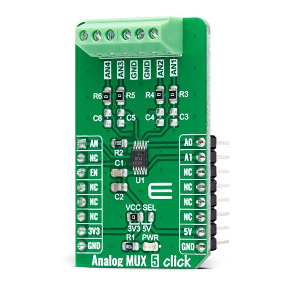
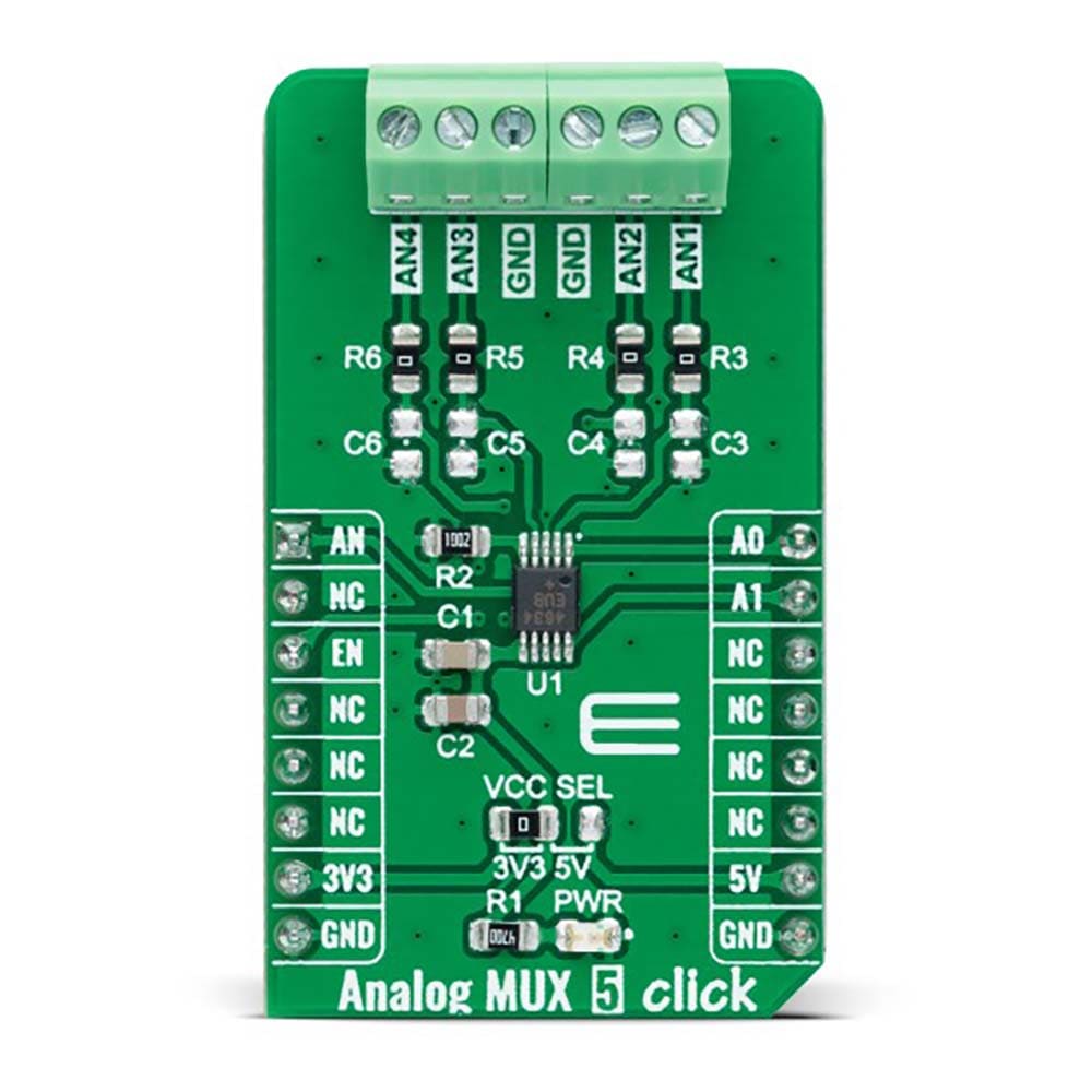
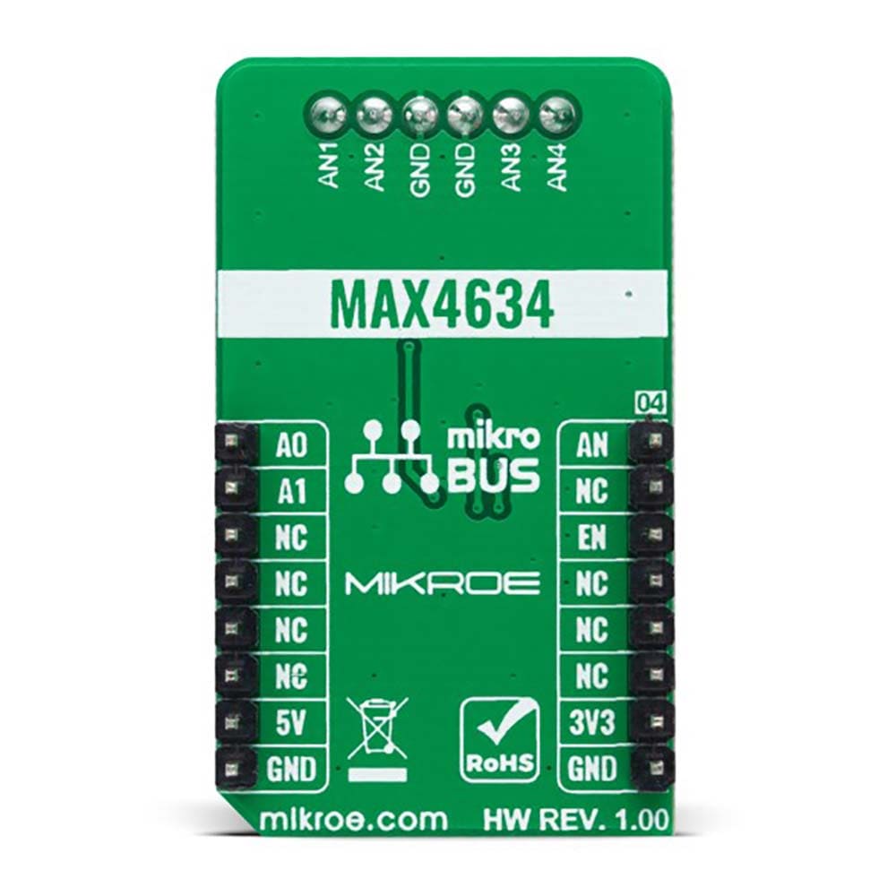
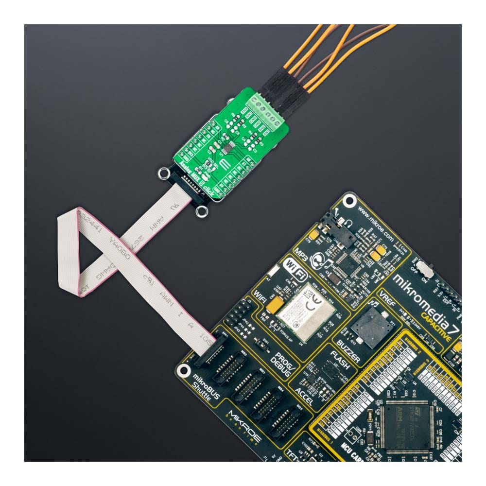
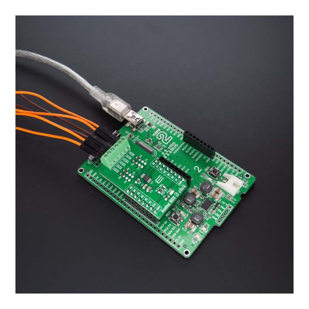
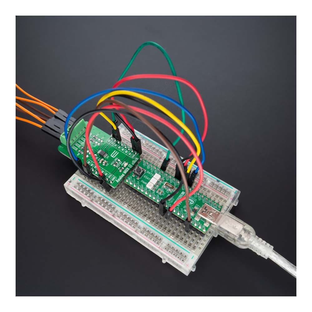
The Analog MUX 5 Click Board™ is a compact add-on board that switches one of many inputs to one output. This board features the MAX4634, a fast, low-voltage four-channel CMOS analog multiplexer from Analog Devices. This low-voltage multiplexer operates from both mikroBUS™ power rails and features 4Ω maximum ON-resistance (RON). CMOS switch construction allows the processing of analog signals within the supply voltage range. It is also characterized by an easy way of management, only through a couple of signals from the mikroBUS™ socket. This Click board™ is suitable for various applications, from industrial and instrumentation to medical, consumer, communications, and more.
The Analog MUX 5 Click Board™ is supported by a mikroSDK compliant library, which includes functions that simplify software development. This Click board™ comes as a fully tested product, ready to be used on a system equipped with the mikroBUS™ socket.
Downloads
La carte Click Board™ Analog MUX 5 est une carte complémentaire compacte qui commute l'une des nombreuses entrées vers une sortie. Cette carte est équipée du MAX4634, un multiplexeur analogique CMOS quatre canaux basse tension rapide d'Analog Devices. Ce multiplexeur basse tension fonctionne à partir des deux rails d'alimentation mikroBUS™ et présente une résistance ON maximale de 4 Ω (RON). La construction du commutateur CMOS permet le traitement des signaux analogiques dans la plage de tension d'alimentation. Elle se caractérise également par un mode de gestion simple, uniquement via quelques signaux provenant de la prise mikroBUS™. Cette carte Click™ convient à diverses applications, de l'industrie et de l'instrumentation au médical, au grand public, aux communications, etc.
La carte Click™ Analog MUX 5 est prise en charge par une bibliothèque compatible mikroSDK, qui comprend des fonctions qui simplifient le développement logiciel. Cette carte Click™ est un produit entièrement testé, prêt à être utilisé sur un système équipé du socket mikroBUS™.
| General Information | |
|---|---|
Part Number (SKU) |
MIKROE-5120
|
Manufacturer |
|
| Physical and Mechanical | |
Weight |
0.02 kg
|
| Other | |
EAN |
8606027388675
|
Frequently Asked Questions
Have a Question?
Be the first to ask a question about this.