Carte à clic H-Bridge 10
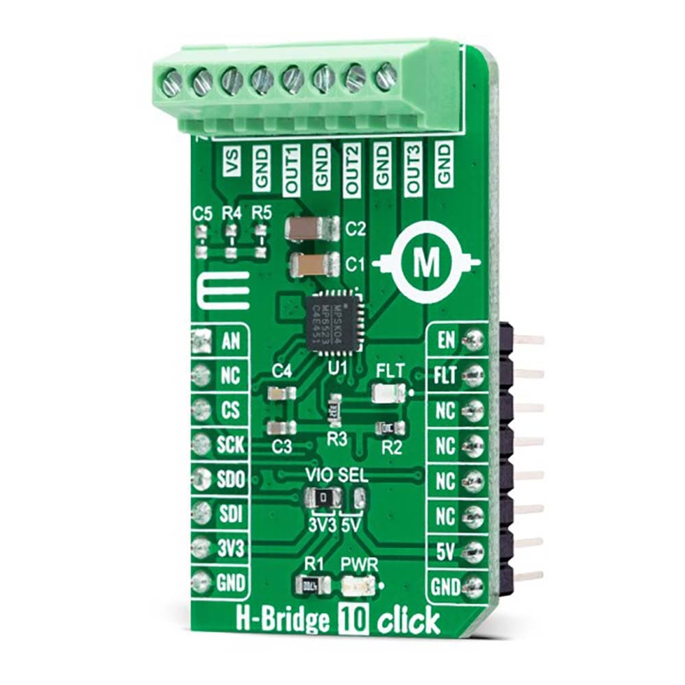
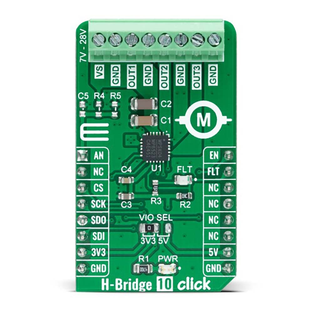
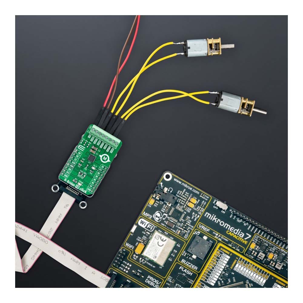
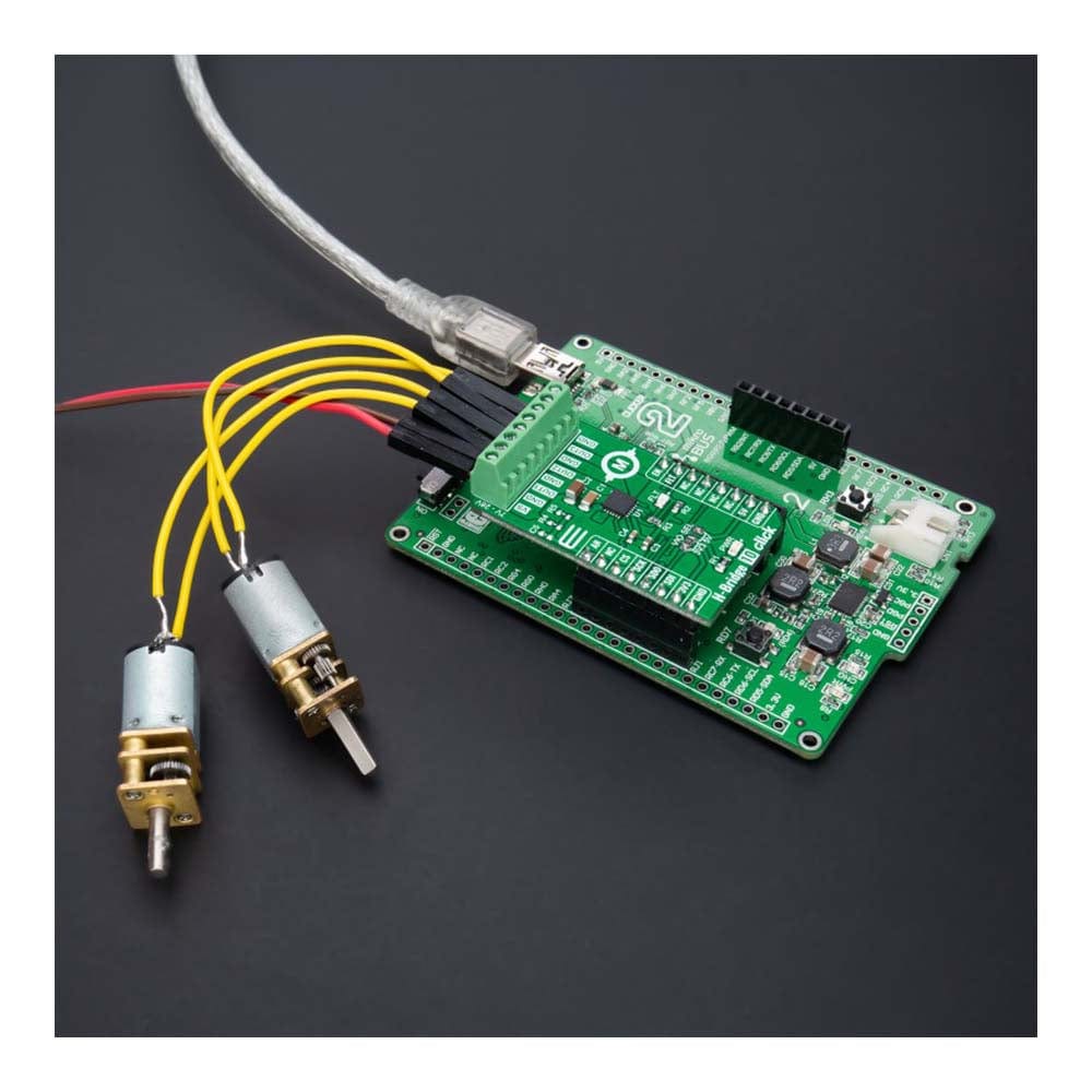
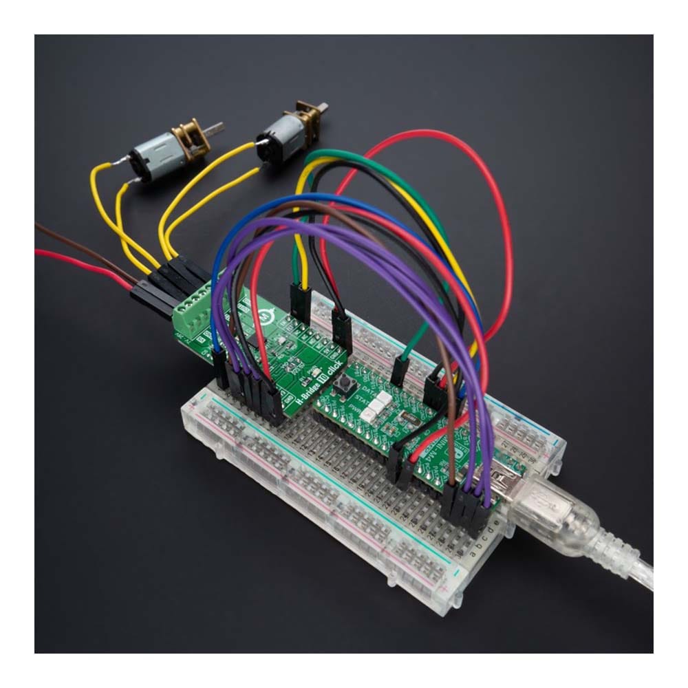
La carte Click Board™ H-Bridge 10 est une carte complémentaire compacte contenant des sorties en pont en H qui vous permettent de contrôler un moteur à courant continu pour qu'il avance ou recule. Cette carte comprend le MP6523, un pilote de sortie DMOS triple en demi-pont avec des MOSFET de puissance intégrés qui peuvent piloter jusqu'à trois charges différentes à partir de systèmes d'alimentation monolithiques (MPS). Le MP6523 est conçu pour une plage de tension de fonctionnement de 7 V à 28 V. Il est configurable par SPI et dispose de diverses fonctions de diagnostic. Les fonctions de protection complètes comprennent la protection contre les courts-circuits (SCP), la protection contre les sous-tensions (UVP) et l'arrêt thermique, ainsi qu'un circuit de vérification de l'existence de l'alimentation électrique embarquée. Cette carte Click™ convient comme pilote de moteur à courant continu à balais multiples pour piloter diverses charges dans les applications automobiles et industrielles, et plus encore.
La carte Click Board™ H-Bridge 10 est supportée par une bibliothèque compatible mikroSDK, qui comprend des fonctions qui simplifient le développement logiciel. Cette carte Click Board™ est un produit entièrement testé, prêt à être utilisé sur un système équipé du socket mikroBUS™.
How Does The H-Bridge 10 Click Board™ Work?
The H-Bridge 10 Click Board™ as its foundation uses the MP6523, a triple, half-bridge motor driver from Monolithic Power Systems (MPS). The MP6523 contains three MOSFET half-bridge outputs that can drive up to three different loads with separate controls for high-side or low-side MOSFETs from a standard serial data interface. It has a low quiescent current in standby mode, making it suitable for many applications. The input voltage ranges from 7V to 28V, with up to 0.9A output current capability per channel. Complete protection features include short-circuit protection, under-voltage protection, and thermal shutdown.
The H-Bridge 10 Click Board™ communicates with MCU through a standard SPI interface and operates at clock rates up to 3MHz, providing data in digital format of 16-bits. It also can be enabled or disabled through the EN pin routed to the PWM pin of the mikroBUS™ socket; hence, offering a switch operation to turn ON/OFF power delivery to the MP6523. It also provides a fault status indication signal, labelled as FLT and routed to the INT pin of the mikroBUS™ socket, alongside its red LED indicator marked as FLT to indicate different fault conditions such as current limit and thermal shutdown.
A unique addition that this board has is checking the existence of an external power supply. By adding resistors R4 and R5, the user can monitor and check the presence of an external power supply on the VS terminal via the voltage divider routed to the AN pin of the mikroBUS™ socket.
The H-Bridge 10 Click Board™ can operate with both 3.3V and 5V logic voltage levels selected via the VCC SEL jumper. This way, it is allowed for both 3.3V and 5V capable MCUs to use the communication lines properly. However, the Click board™ comes equipped with a library that contains easy-to-use functions and an example code that can be used, as a reference, for further development.
SPECIFICATIONS
Type | Brushed |
Applications | The H-Bridge 10 Click Board™ can be used as a multiple brushed DC motor driver for driving various loads in automotive and industrial applications, and more |
On-board modules | MP6523 - triple, half-bridge motor driver from Monolithic Power Systems (MPS) |
Key Features | Integrated power MOSFETs drive up to three different loads, low power consumption, high level of programming, high level diagnostics, protection features, and more |
Interface | Analog,SPI |
Compatibility | mikroBUS |
Click board size | M (42.9 x 25.4 mm) |
Input Voltage | 3.3V or 5V,External |
PINOUT DIAGRAM
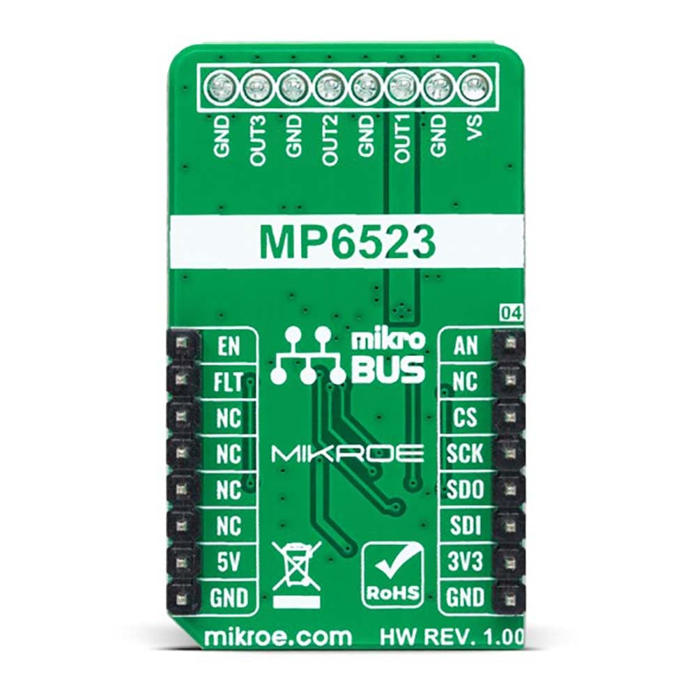
This table shows how the pinout of the H-Bridge 10 Click Board™ corresponds to the pinout on the mikroBUS™ socket (the latter shown in the two middle columns).
Notes | Pin | Pin | Notes | ||||
---|---|---|---|---|---|---|---|
Power Supply Check | AN | 1 | AN | PWM | 16 | EN | Enable |
NC | 2 | RST | INT | 15 | FLT | Fault Indication | |
SPI Chip Select | CS | 3 | CS | RX | 14 | NC | |
SPI Clock | SCK | 4 | SCK | TX | 13 | NC | |
SPI Data OUT | SDO | 5 | MISO | SCL | 12 | NC | |
SPI Data IN | SDI | 6 | MOSI | SDA | 11 | NC | |
Power Supply | 3.3V | 7 | 3.3V | 5V | 10 | 5V | Power Supply |
Ground | GND | 8 | GND | GND | 9 | GND | Ground |
ONBOARD SETTINGS AND INDICATORS
Label | Name | Default | Description |
---|---|---|---|
LD1 | PWR | - | Power LED Indicator |
LD2 | FLT | - | Fault LED Indicator |
JP1 | VCC SEL | Left | Logic Level Voltage Selection 3V3/5V: Left position 3V3, Right position 5V |
R4-R5 | R4-R5 | Unpopulated | Power Supply Existence Check Jumpers |
H-BRIDGE 10 CLICK ELECTRICAL SPECIFICATIONS
Description | Min | Typ | Max | Unit |
---|---|---|---|---|
Supply Voltage VCC | 3.3 | - | 5 | V |
External Supply Voltage VS | 7 | - | 28 | V |
Maximum Output Current (per channel) | - | - | 0.9 | A |
Operating Temperature Range | -40 | +25 | +120 | °C |
Software Support
We provide a library for the H-Bridge 10 Click Board™ as well as a demo application (example), developed using MikroElektronika compilers. The demo can run on all the main MikroElektronika development boards.
The package can be downloaded/installed directly from NECTO Studio The package Manager (recommended), downloaded from our LibStock™ or found on MikroE Github account.
Library Description
This library contains API for the H-Bridge 10 Click Board™ driver.
Key functions
-
hbridge10_set_output_state
This function sets the output channel state. -
hbridge10_get_status
This function reads the status of output register. -
hbridge10_get_fault_pin
This function returns the fault (FLT) pin logic state.
Example Description
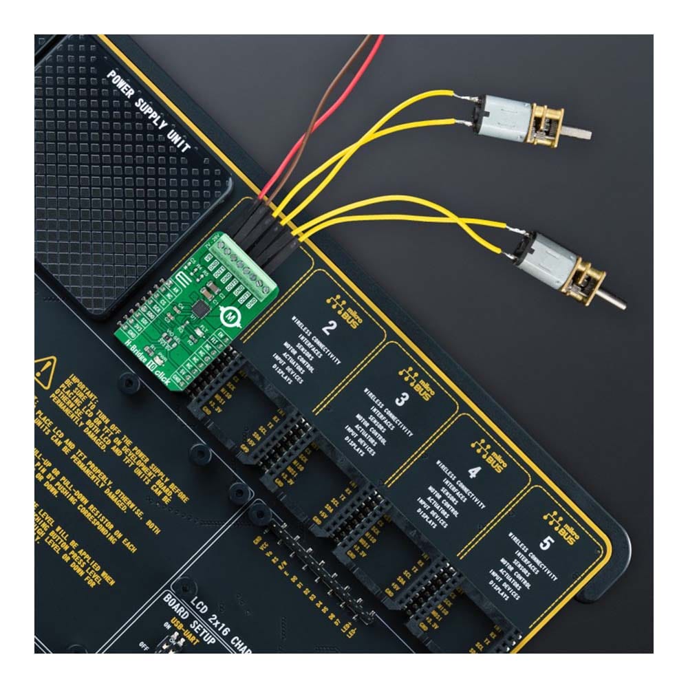
This example demonstrates the use of the H-Bridge 10 Click Board™ by driving the motors connected between OUT1-OUT2 and OUT2-OUT3 in both directions.
void application_task ( void )
{
uint16_t status;
if ( ( HBRIDGE10_OK == hbridge10_set_output_state ( &hbridge10, HBRIDGE10_CHANNEL_OUT1, HBRIDGE10_OUT_HIGH ) ) &&
( HBRIDGE10_OK == hbridge10_set_output_state ( &hbridge10, HBRIDGE10_CHANNEL_OUT2, HBRIDGE10_OUT_LOW ) ) &&
( HBRIDGE10_OK == hbridge10_set_output_state ( &hbridge10, HBRIDGE10_CHANNEL_OUT3, HBRIDGE10_OUT_HIGH ) ) )
{
Delay_ms ( 100 );
if ( HBRIDGE10_OK == hbridge10_get_status ( &hbridge10, &status ) )
{
hbridge10_display_status ( status );
Delay_ms ( 3000 );
}
}
if ( ( HBRIDGE10_OK == hbridge10_set_output_state ( &hbridge10, HBRIDGE10_CHANNEL_OUT1, HBRIDGE10_OUT_LOW ) ) &&
( HBRIDGE10_OK == hbridge10_set_output_state ( &hbridge10, HBRIDGE10_CHANNEL_OUT2, HBRIDGE10_OUT_HIGH ) ) &&
( HBRIDGE10_OK == hbridge10_set_output_state ( &hbridge10, HBRIDGE10_CHANNEL_OUT3, HBRIDGE10_OUT_LOW ) ) )
{
Delay_ms ( 100 );
if ( HBRIDGE10_OK == hbridge10_get_status ( &hbridge10, &status ) )
{
hbridge10_display_status ( status );
Delay_ms ( 3000 );
}
}
}
The full application code, and ready to use projects can be installed directly from NECTO Studio The package Manager (recommended), downloaded from our LibStock™ or found on MikroE Github account.
Other MikroE Libraries used in the example:
- MikroSDK.Board
- MikroSDK.Log
- Click.HBridge10
Additional Notes and Information
Depending on the development board you are using, you may need a USB UART click, USB UART 2 Click or RS232 Click to connect to your PC, for development systems with no UART to USB interface available on the board. UART terminal is available in all MikroElektronika compilers.
MIKROSDK
The H-Bridge 10 Click Board™ is supported with mikroSDK - MikroElektronika Software Development Kit. To ensure proper operation of mikroSDK compliant Click board™ demo applications, mikroSDK should be downloaded from the LibStock and installed for the compiler you are using.
Carte à clic H-Bridge 10
Frequently Asked Questions
Have a Question?
Be the first to ask a question about this.