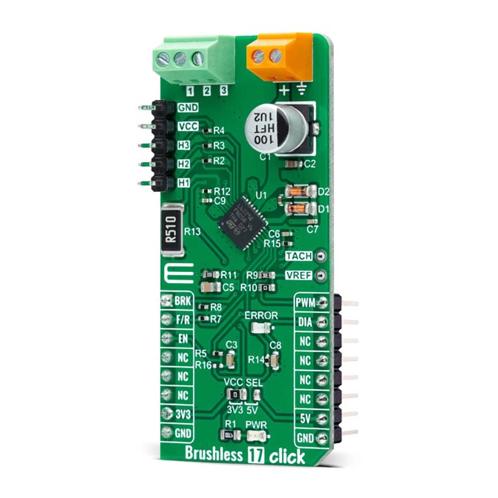
Carte à clic sans balais 17
Key Features
- Faible consommation d'énergie, détection et protection contre les surintensités, sortie de diagnostic, contrôleur de courant PWM, fonction de freinage, etc.
- Basé sur le L6229Q - Pilote de moteur BLDC triphasé entièrement intégré DMOS avec protection contre les surintensités de STMicroelectronics
- Peut être utilisé pour piloter des moteurs à courant continu sans balais triphasés avec des courants jusqu'à 1 A CC
- Interface PWM
Overview
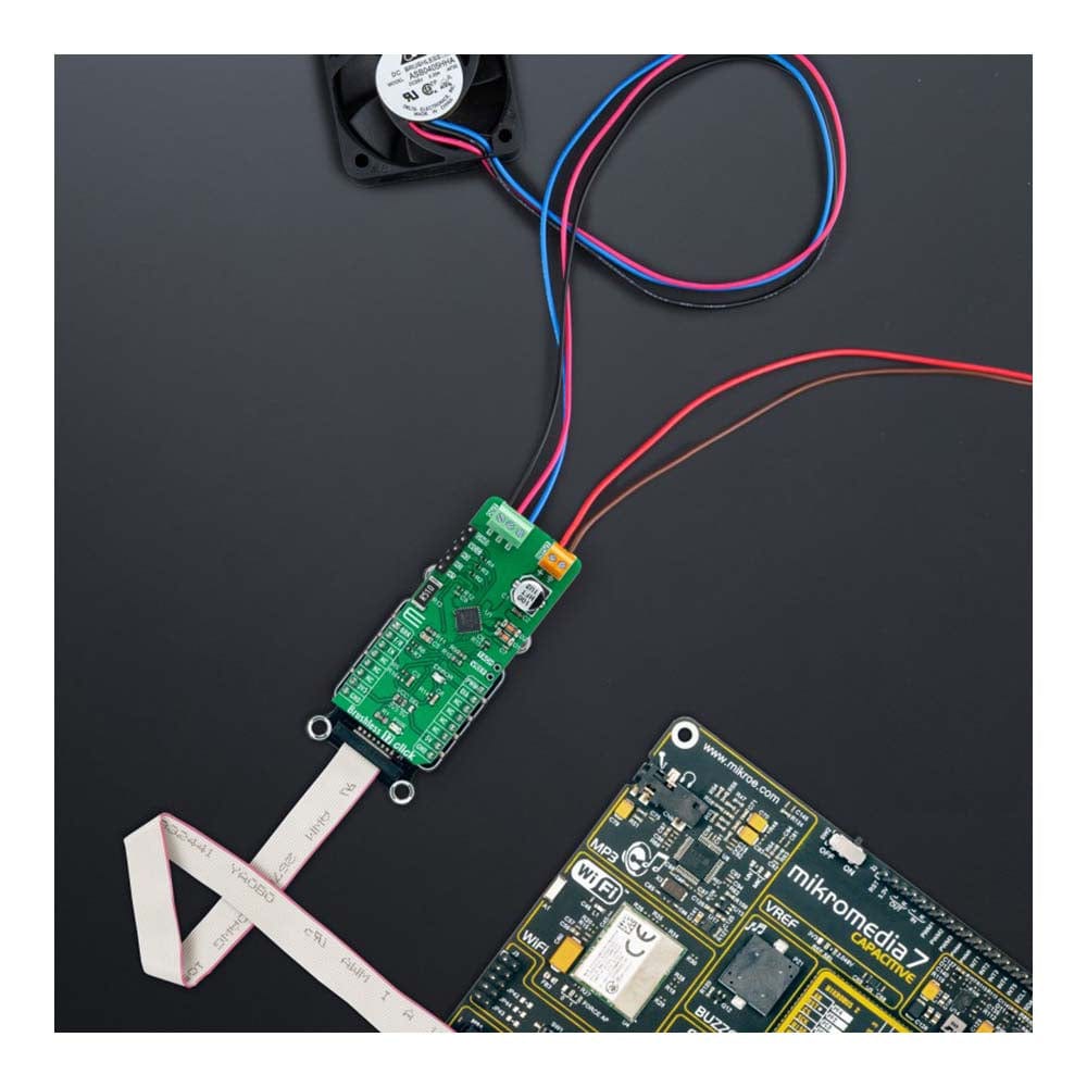
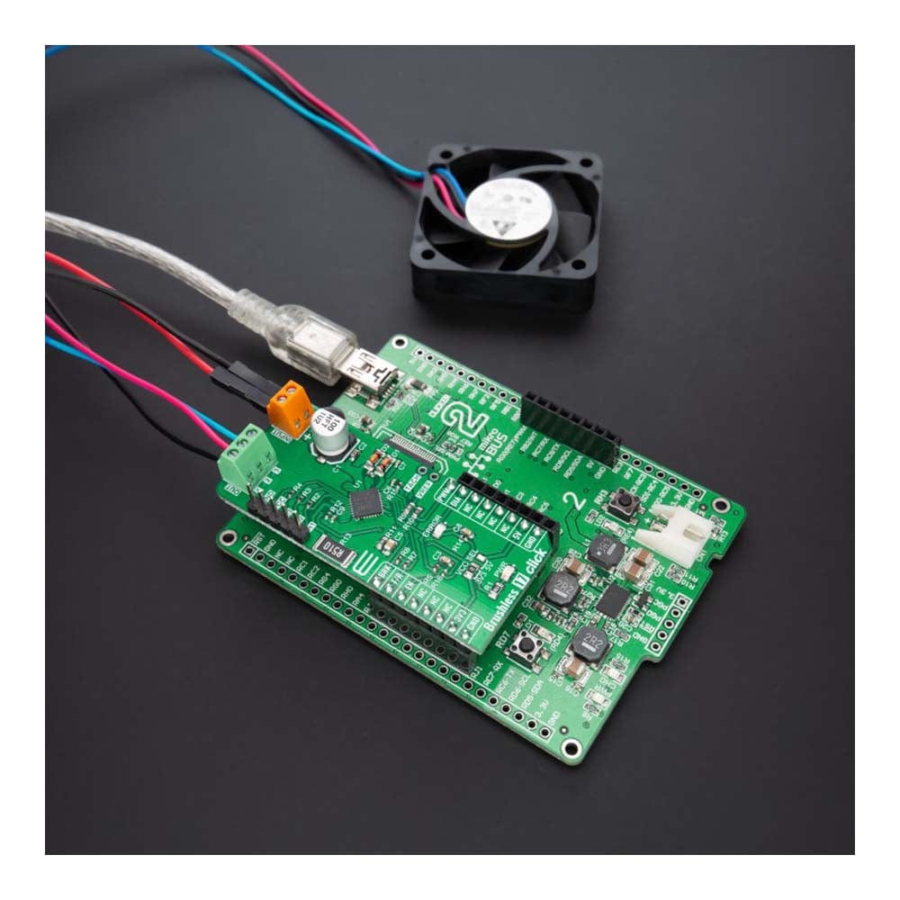
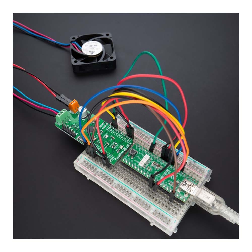
La carte Click Board™ Brushless 17 est une carte complémentaire compacte adaptée au contrôle des moteurs à courant continu sans balais (BLDC) avec n'importe quel microcontrôleur. Cette carte est équipée du pilote de moteur BLDC triphasé entièrement intégré DMOS L6229Q avec protection contre les surintensités de STMicroelectronics. Ce pilote de moteur combine des transistors de puissance DMOS isolés avec des circuits CMOS et bipolaires sur la même puce, réalisés en technologie multi-puissance BCD (Bipolar-CMOS-DMOS). Il comprend tous les circuits pour un entraînement de moteur BLDC triphasé, y compris un pont DMOS triphasé, un contrôleur de courant PWM à temps d'arrêt constant et la logique de décodage pour les capteurs à effet Hall à extrémité unique qui génèrent la séquence requise pour l'étage de puissance. Cette carte Click™ constitue la solution parfaite pour piloter des moteurs à courant continu sans balais triphasés avec des courants allant jusqu'à 1 A CC.
La carte Click Board™ Brushless 17 est supportée par une bibliothèque compatible mikroSDK, qui comprend des fonctions qui simplifient le développement logiciel. Cette carte Click Board™ est livrée sous la forme d'un produit entièrement testé, prêt à être utilisé sur un système équipé du socket mikroBUS™.
How Does The Brushless 17 Click Board™ Work?
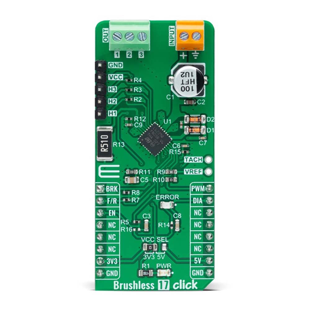
The Brushless 17 Click Board™ as its foundation uses the L6229Q, DMOS fully integrated three-phase BLDC motor driver with overcurrent protection from STMicroelectronics. It combines a three-phase bridge, which consists of 6 power MOSFETs. Switching patterns are generated by the PWM current controller and the hall-effect sensor decoding logic, which represents a combinatory logic that provides the appropriate driving signals for the three-phase bridge outputs (1, 2, and 3). Drive signals are based on the signals coming from the three hall sensors, H1, H2, and H3, applicable on the upper-left header reserved for Hall sensor connection. These hall sensors detect rotor position in a 3-phase BLDC motor.
The L6229Q can perform PWM current control, with analog reference voltage provided at its VREF pin. This control can be achieved by using a PWM signal from the mikroBUS™ socket or applying an external reference voltage. When using PWM signal from mikroBUS™, leave R10 resistor populated. This is a straightforward way of obtaining a variable voltage without using a DAC, using a low-pass filter to filter the PWM signal. Alternatively, a fixed reference voltage can also be obtained through an external voltage supply on the VREF pin. This board also provides a tachometer function, a TACH output signal, which can be used to implement a simple frequency-to-voltage converter (speed loop control).
The Brushless 17 Click Board™ communicates with MCU using several GPIO pins. The Enable pin, labelled as EN and routed to the CS pin of the mikroBUS™ socket, optimizes power consumption used for power ON/OFF purposes (performs Start and Stop controls of the motor operation), while AN pin labelled as BRK allows users to implement the brake function. The F/R pin, routed on the RST pin of the mikroBUS™ socket, is used to select the direction of motor rotation (forward/reverse). Besides, it is possible to detect operational irregularities, such as overcurrent and thermal detection, where an indication of such a condition is performed using the red LED indicator labelled as ERROR routed on the INT pin of the mikroBUS™ socket, labelled as DIA.
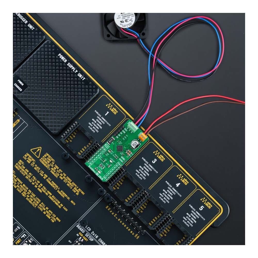
This board supports an external power supply for the motor, which can be connected to the input terminal labelled as INPUT and should be within the range of 8V to 52V, while the BLDC motor coils can be connected to the terminals labelled as 1, 2, and 3.
The Brushless 17 Click Board™ can operate with both 3.3V and 5V logic voltage levels selected via the VCC SEL jumper. This way, it is allowed for both 3.3V and 5V capable MCUs to use the communication lines properly. However, the Click board™ comes equipped with a library containing easy-to-use functions and an example code that can be used, as a reference, for further development.
SPECIFICATIONS
Type | Brushless |
Applications | The Brushless 17 Click Board™ can be used driving three-phase brushless DC motors with currents up to 1A DC |
On-board modules | L6229Q - DMOS fully integrated three-phase BLDC motor driver with overcurrent protection from STMicroelectronics |
Key Features | Low power consumption, overcurrent detection and protection, diagnostic output, PWM current controller, brake function, and more |
Interface | GPIO,PWM |
Compatibility | mikroBUS |
Click board size | L (57.15 x 25.4 mm) |
Input Voltage | 3.3V or 5V,External |
PINOUT DIAGRAM
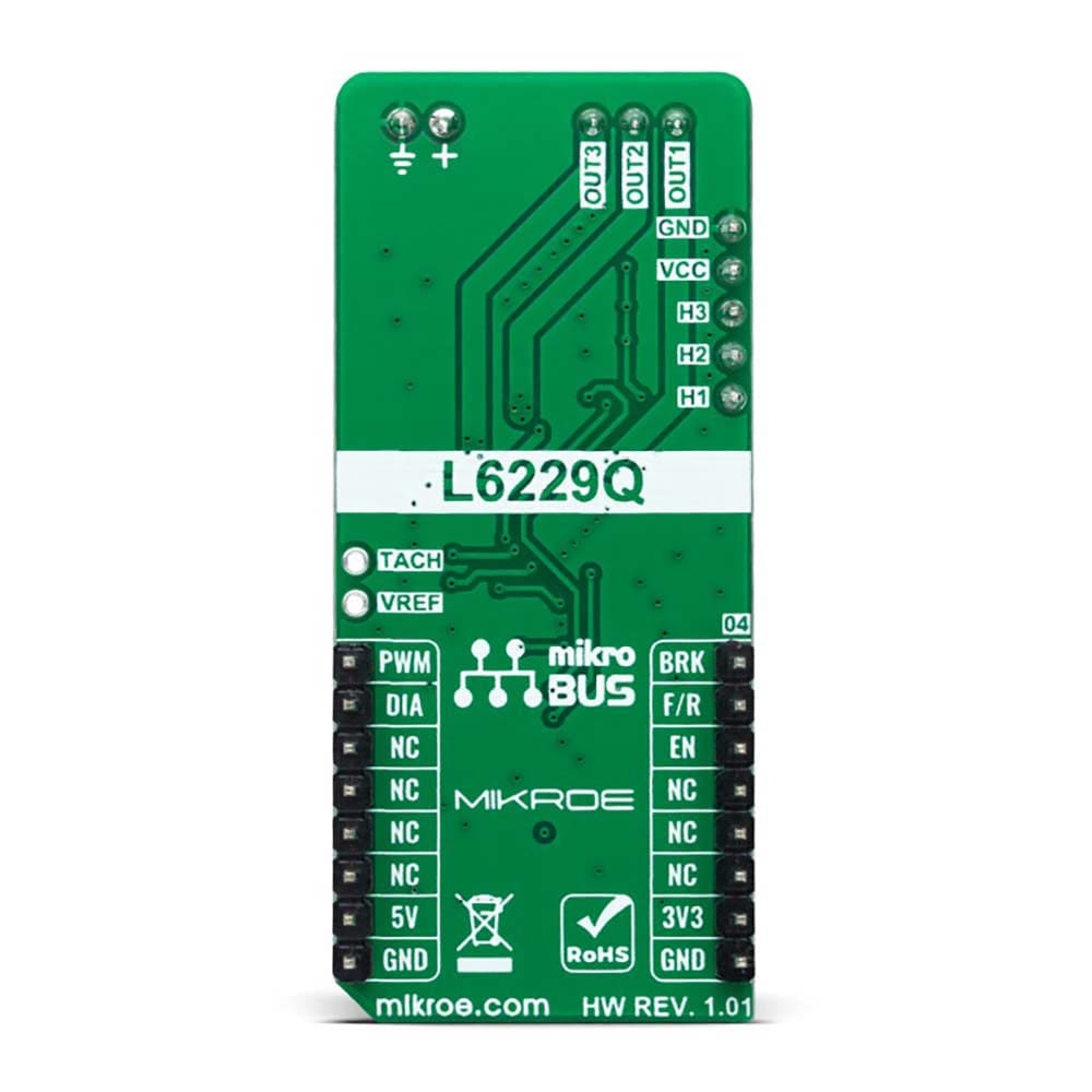
This table shows how the pinout of the Brushless 17 Click Board™ corresponds to the pinout on the mikroBUS™ socket (the latter shown in the two middle columns).
Notes | Pin | Pin | Notes | ||||
---|---|---|---|---|---|---|---|
Brake | BRK | 1 | AN | PWM | 16 | PWM | PWM Signal |
Forward/Reverse Direction | F/R | 2 | RST | INT | 15 | DIA | Fault Interrupt |
Enable | EN | 3 | CS | RX | 14 | NC | |
NC | 4 | SCK | TX | 13 | NC | ||
NC | 5 | MISO | SCL | 12 | NC | ||
NC | 6 | MOSI | SDA | 11 | NC | ||
Power Supply | 3.3V | 7 | 3.3V | 5V | 10 | 5V | Power Supply |
Ground | GND | 8 | GND | GND | 9 | GND | Ground |
ONBOARD SETTINGS AND INDICATORS
Label | Name | Default | Description |
---|---|---|---|
LD1 | PWR | - | Power LED Indicator |
LD2 | ERROR | - | Fault Condition LED Indicator |
J1 | - | Populated | Hall Sensor Connection Header |
J2 | - | Unpopulated | Tachometer for Speed Contol Loop pin / External Reference Voltage for PWM Current Control |
BRUSHLESS 17 CLICK ELECTRICAL SPECIFICATIONS
Description | Min | Typ | Max | Unit |
---|---|---|---|---|
Supply Voltage VCC | 3.3 | - | 5 | V |
External Supply Voltage INPUT | 8 | - | 52 | V |
Maximum Output Current | - | - | 1.4 | A |
Operating Temperature Range | -25 | +25 | +120 | °C |
Software Support
We provide a library for the Brushless 17 Click Board™ as well as a demo application (example), developed using MikroElektronika compilers. The demo can run on all the main MikroElektronika development boards.
The package can be downloaded/installed directly from NECTO Studio The package Manager (recommended), downloaded from our LibStock™ or found on MikroE Github account.
Library Description
This library contains API for the Brushless 17 Click Board™ driver.
Key functions
-
brushless17_set_duty_cycle
This function sets the PWM duty cycle in percentages ( Range[ 0..1 ] ). -
brushless17_switch_direction
This function switches the direction by toggling the DIR pin state. -
brushless17_get_diagnostic_pin
This function returns the DIAG pin logic state.
Example Description
This example demonstrates the use of the Brushless 17 Click Board™ by driving the motor in both directions at different speeds.
void application_task ( void )
{
static int8_t duty_cnt = 4;
static int8_t duty_inc = 1;
float duty = duty_cnt / 10.0;
brushless17_set_duty_cycle ( &brushless17, duty );
log_printf( &logger, "> Duty: %d%%rn", ( uint16_t )( duty_cnt * 10 ) );
duty_cnt += duty_inc;
if ( 8 == duty_cnt )
{
duty_inc = -1;
}
else if ( 3 == duty_cnt )
{
duty_inc = 1;
duty_cnt = 4;
log_printf( &logger, " Switch directionrnn" );
brushless17_switch_direction ( &brushless17 );
}
if ( !brushless17_get_diagnostic_pin ( &brushless17 ) )
{
log_info ( &logger, " An overcurrent or overtemperature event has occured " );
}
Delay_ms( 500 );
}
The full application code, and ready to use projects can be installed directly from NECTO Studio The package Manager (recommended), downloaded from our LibStock™ or found on MikroE Github account.
Other MikroE Libraries used in the example:
- MikroSDK.Board
- MikroSDK.Log
- Click.Brushless17
Additional Notes and Information
Depending on the development board you are using, you may need USB UART Click Board™, USB UART 2 Click or RS232 Click to connect to your PC, for development systems with no UART to USB interface available on the board. UART terminal is available in all MikroElektronika compilers.
MIKROSDK
The Brushless 17 Click Board™ is supported with mikroSDK - MikroElektronika Software Development Kit. To ensure proper operation of mikroSDK compliant Click board™ demo applications, mikroSDK should be downloaded from the LibStock and installed for the compiler you are using.
Frequently Asked Questions
Have a Question?
Be the first to ask a question about this.