


Mikroelektronika d.o.o.
Chargeur 18 Click Board
Chargeur 18 Click Board
SKU: MIKROE-4990
Impossible de charger la disponibilité du service de retrait

Overview
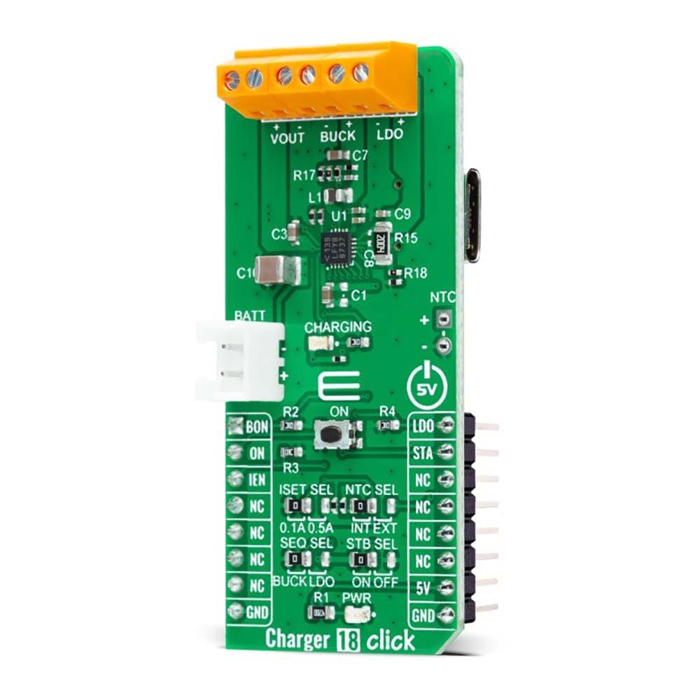
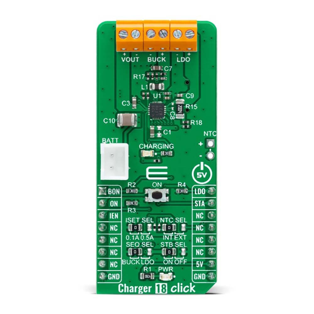
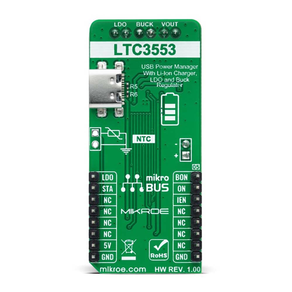
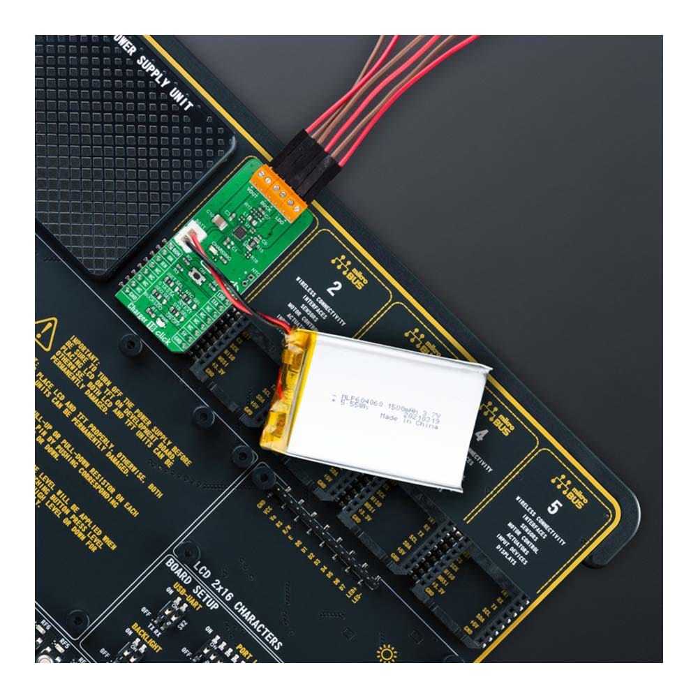
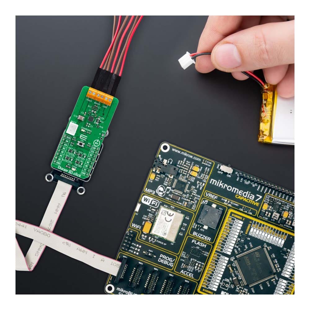
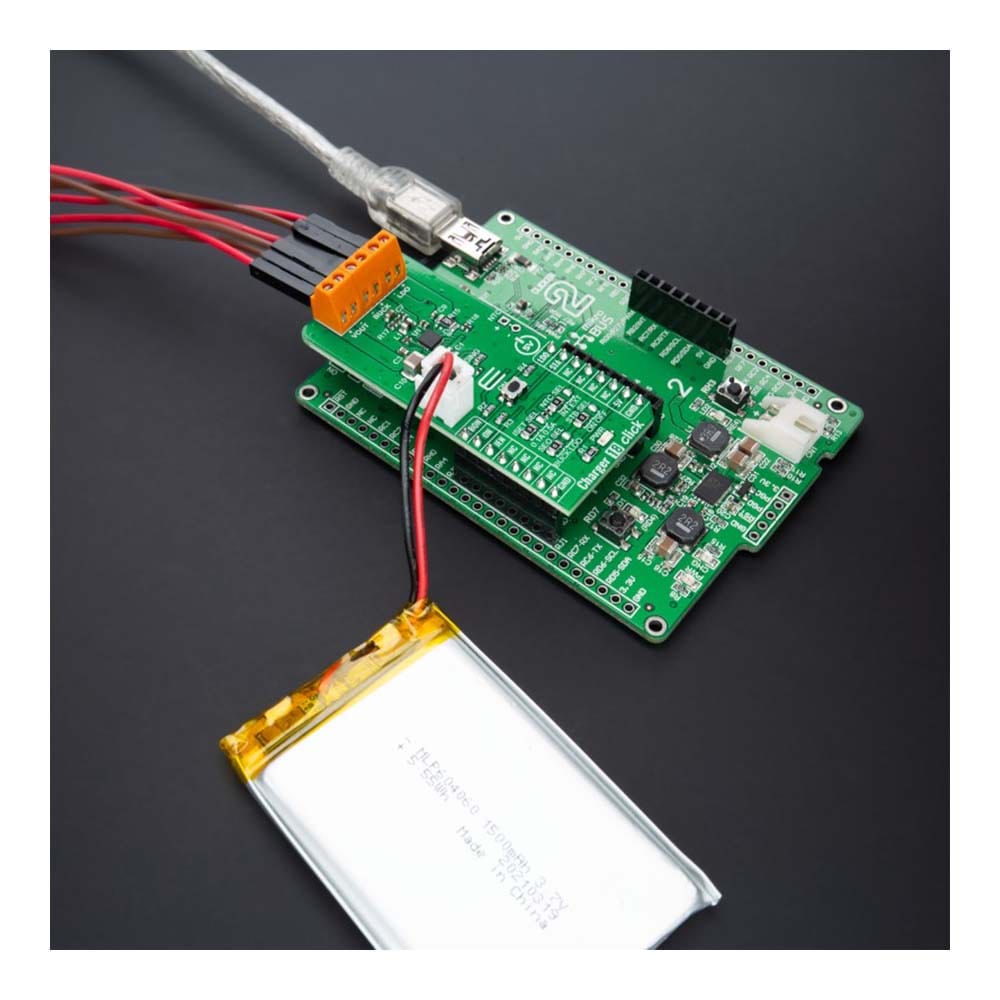
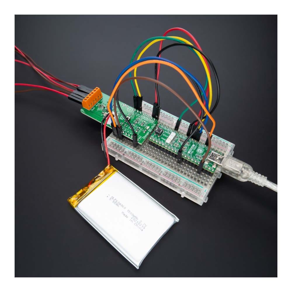
The Charger 18 Click Board™ is a compact add-on board representing a single-cell battery charger. This board features the LTC3553, a micropower, highly integrated power management, and battery charger for single-cell Li-Ion/Polymer battery applications from Analog Devices. Designed specifically for USB applications, it also includes a PowerPath manager with automatic load prioritization and input current limit, a battery charger, and numerous internal protection features. It also indicates a battery charge state, and it comes with a synchronous 200mA buck regulator and a 150mA low dropout linear regulator (LDO). This Click board™ is suitable as a Li-Ion/Polymer battery charger for portable devices and accessories, power tools, and more.
The Charger 18 Click Board™ is supported by a mikroSDK compliant library, which includes functions that simplify software development. This Click board™ comes as a fully tested product, ready to be used on a system equipped with the mikroBUS™ socket.
Downloads
Le chargeur 18 Click Board™ est une carte complémentaire compacte représentant un chargeur de batterie à cellule unique. Cette carte comprend le LTC3553, un chargeur de batterie et de gestion de l'alimentation hautement intégré à micropuissance pour les applications de batterie Li-Ion/Polymère à cellule unique d'Analog Devices. Conçu spécifiquement pour les applications USB, il comprend également un gestionnaire PowerPath avec priorisation automatique de la charge et limite du courant d'entrée, un chargeur de batterie et de nombreuses fonctions de protection internes. Il indique également l'état de charge de la batterie et est livré avec un régulateur abaisseur synchrone de 200 mA et un régulateur linéaire à faible chute de tension (LDO) de 150 mA. Ce Click board™ convient comme chargeur de batterie Li-Ion/Polymère pour les appareils et accessoires portables, les outils électriques, etc.
La carte Click™ Charger 18 est prise en charge par une bibliothèque compatible mikroSDK, qui comprend des fonctions qui simplifient le développement logiciel. Cette carte Click™ est un produit entièrement testé, prêt à être utilisé sur un système équipé de la prise mikroBUS™.
| General Information | |
|---|---|
Part Number (SKU) |
MIKROE-4990
|
Manufacturer |
|
| Physical and Mechanical | |
Weight |
0.02 kg
|
| Other | |
EAN |
8606027389368
|
Frequently Asked Questions
Have a Question?
Be the first to ask a question about this.