


Mikroelektronika d.o.o.
Tableau à clic CapSense 2
Tableau à clic CapSense 2
SKU: MIKROE-4982
Impossible de charger la disponibilité du service de retrait


Key Features
Overview
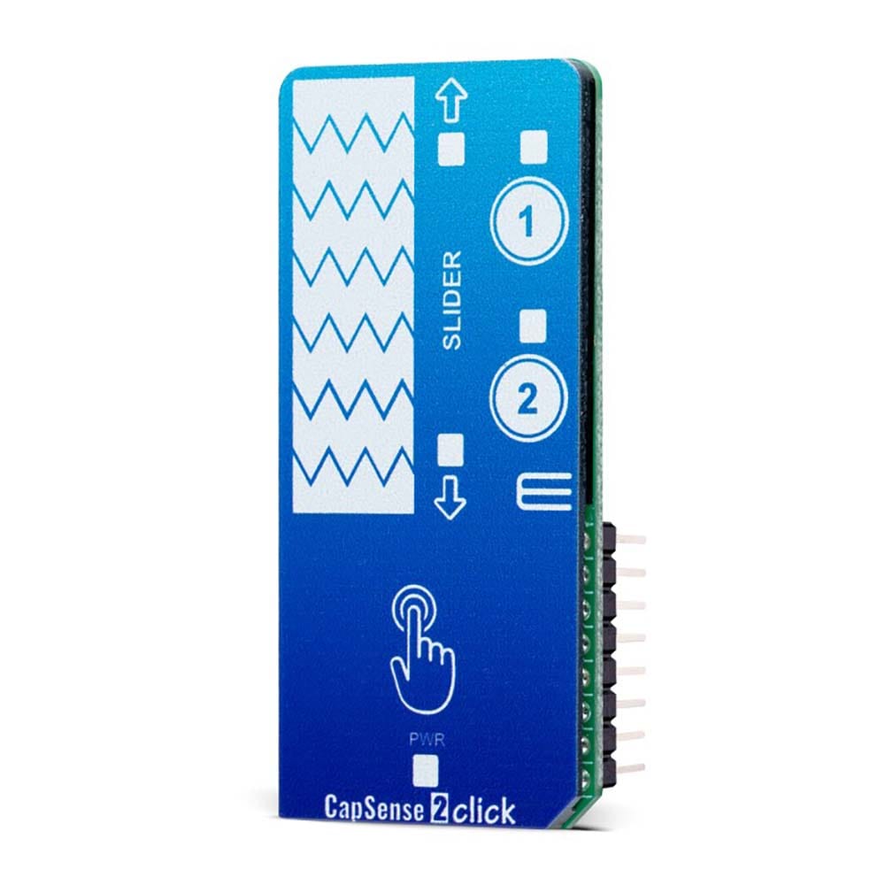
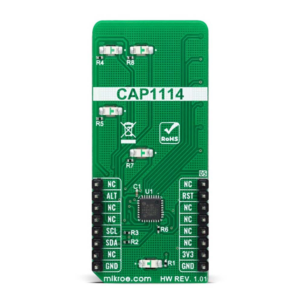
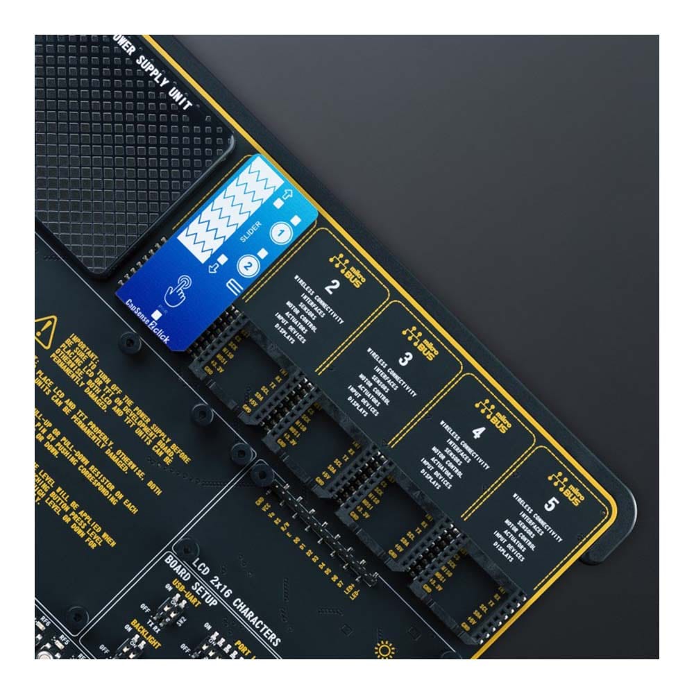
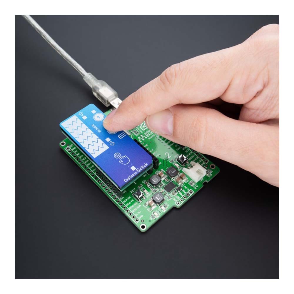
The CapSense 2 Click Board™ is a compact add-on board that easily integrates projected capacitive touch into user's applications. This board features the CAP1114, a multi-channel capacitive touch sensor that takes human body capacitance as an input and directly provides the real-time sensor information via the I2C serial interface from Microchip. This board contains capacitive sensing elements, a 7-segment slider, two buttons, and four LED indicators that visually detect the activation on some of these parts. This Click board™ offers reliable and accurate sensing for any application that uses capacitive touch sensing functions.
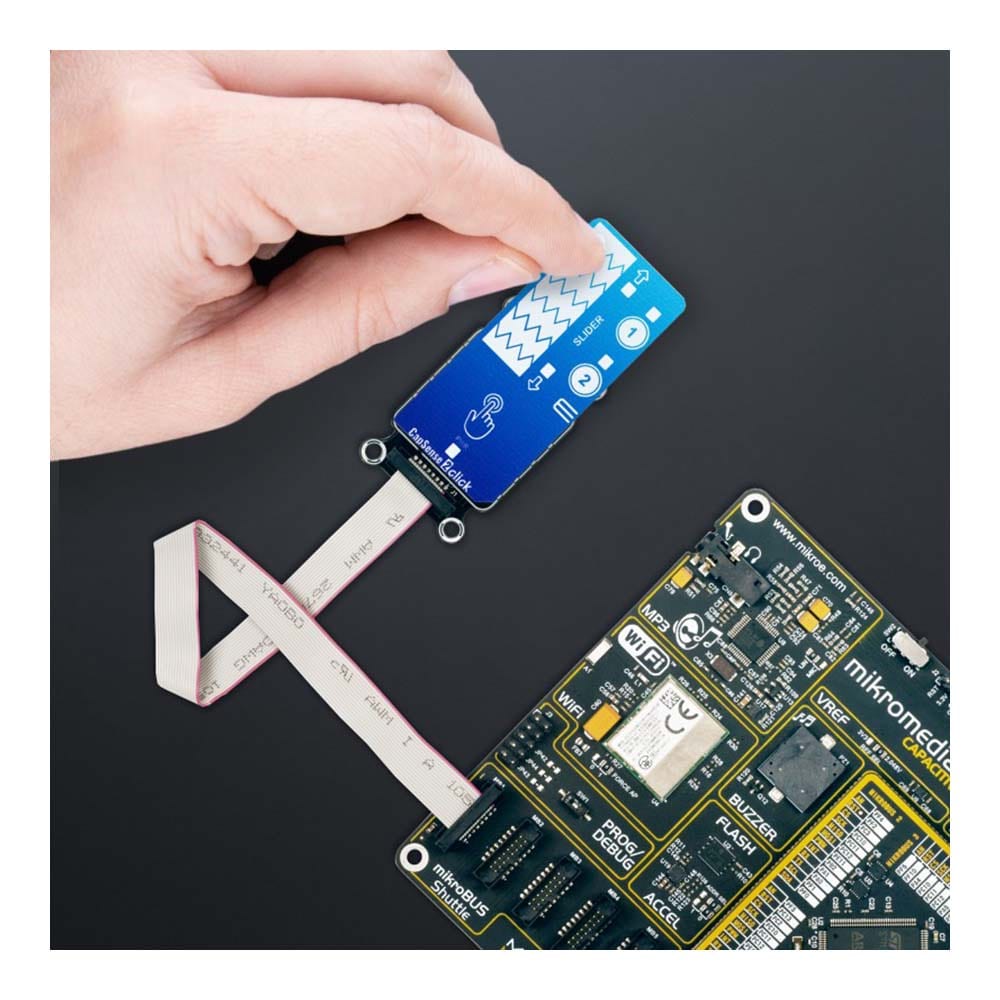
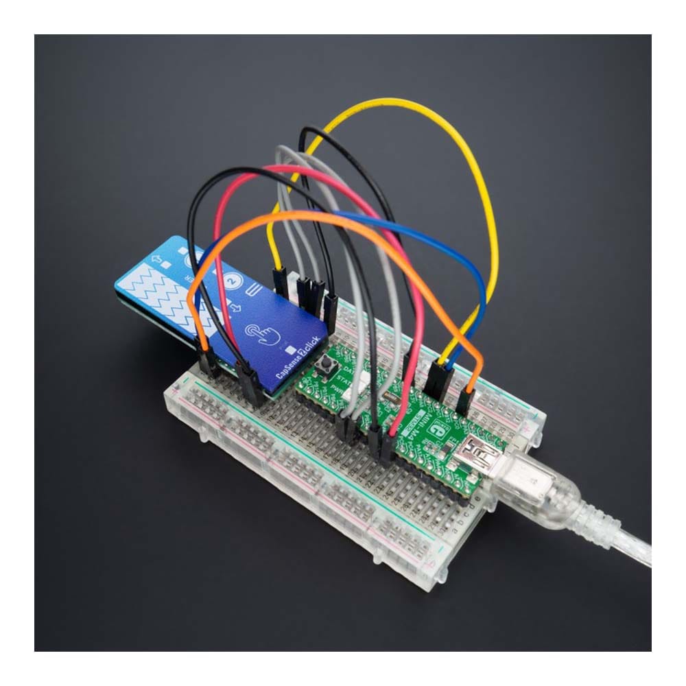
The CapSense 2 Click Board™ is supported by a mikroSDK compliant library, which includes functions that simplify software development. This Click board™ comes as a fully tested product, ready to be used on a system equipped with the mikroBUS™ socket.
Downloads
La carte Click Board™ CapSense 2 est une carte complémentaire compacte qui intègre facilement la technologie tactile capacitive projetée dans les applications de l'utilisateur. Cette carte est équipée du CAP1114, un capteur tactile capacitif multicanal qui prend la capacité du corps humain comme entrée et fournit directement les informations du capteur en temps réel via l'interface série I2C de Microchip. Cette carte contient des éléments de détection capacitifs, un curseur à 7 segments, deux boutons et quatre indicateurs LED qui détectent visuellement l'activation de certaines de ces pièces. Cette carte Click Board™ offre une détection fiable et précise pour toute application qui utilise des fonctions de détection tactile capacitive.
La carte Click™ CapSense 2 est supportée par une bibliothèque compatible mikroSDK, qui comprend des fonctions qui simplifient le développement logiciel. Cette carte Click™ est livrée sous la forme d'un produit entièrement testé, prêt à être utilisé sur un système équipé du socket mikroBUS™.
| General Information | |
|---|---|
Part Number (SKU) |
MIKROE-4982
|
Manufacturer |
|
| Physical and Mechanical | |
Weight |
0.03 kg
|
| Other | |
EAN |
8606027389290
|
Frequently Asked Questions
Have a Question?
Be the first to ask a question about this.