


Mikroelektronika d.o.o.
Carte de pilote LED 12 Click
Carte de pilote LED 12 Click
Impossible de charger la disponibilité du service de retrait
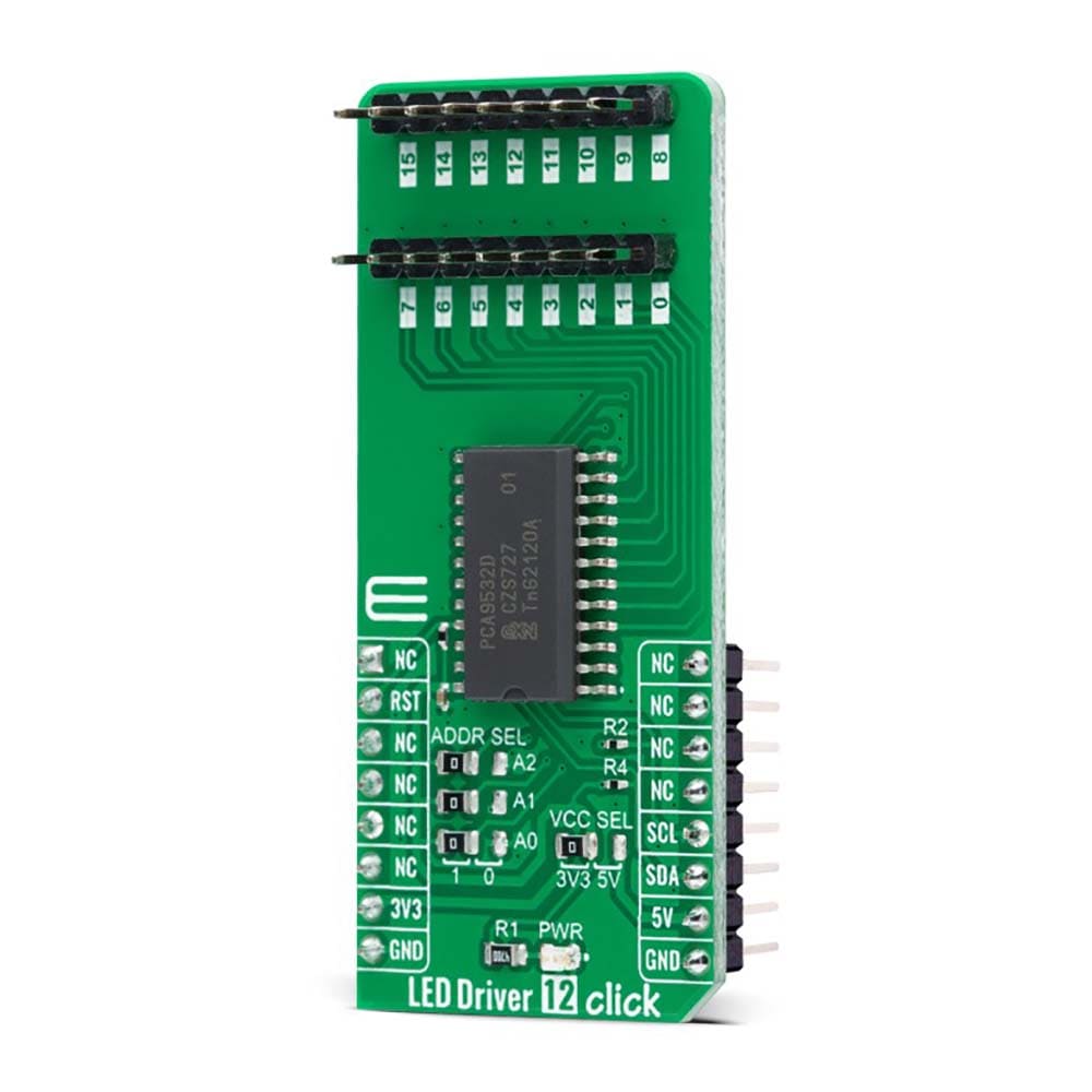
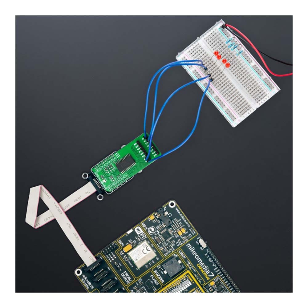
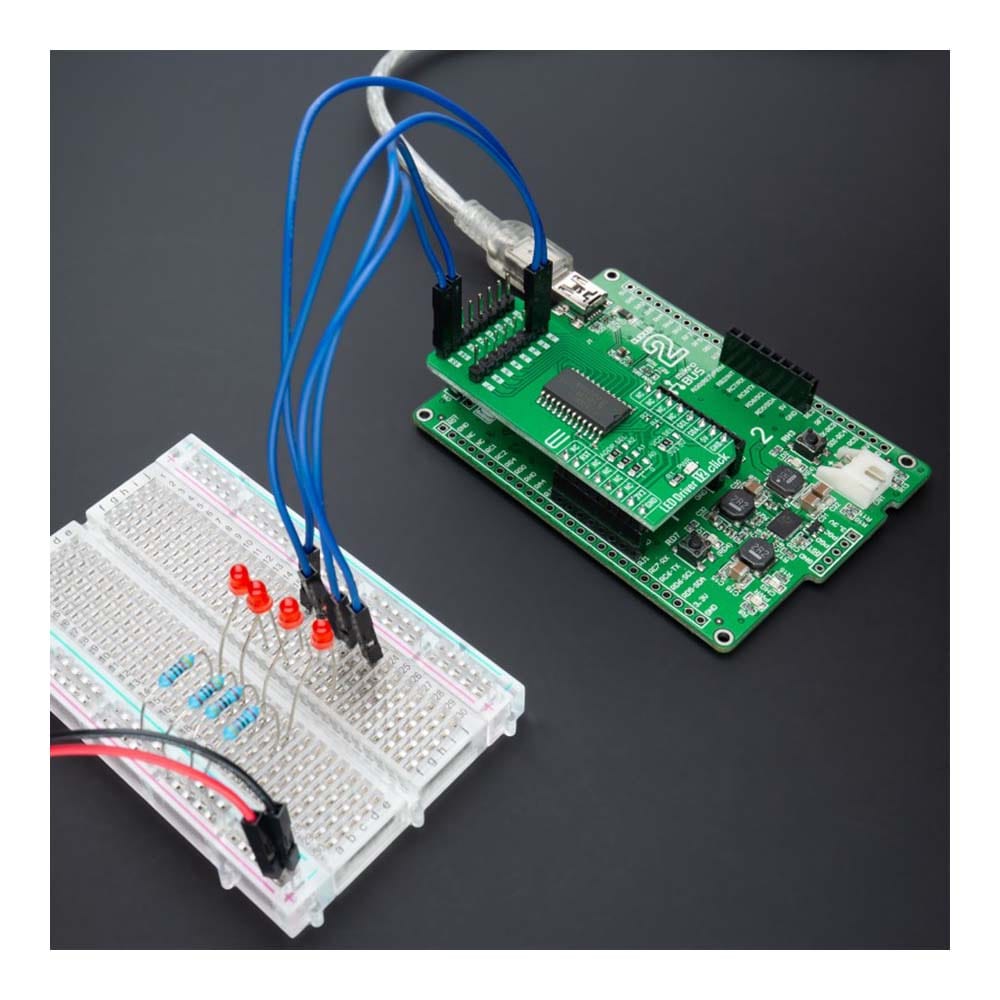
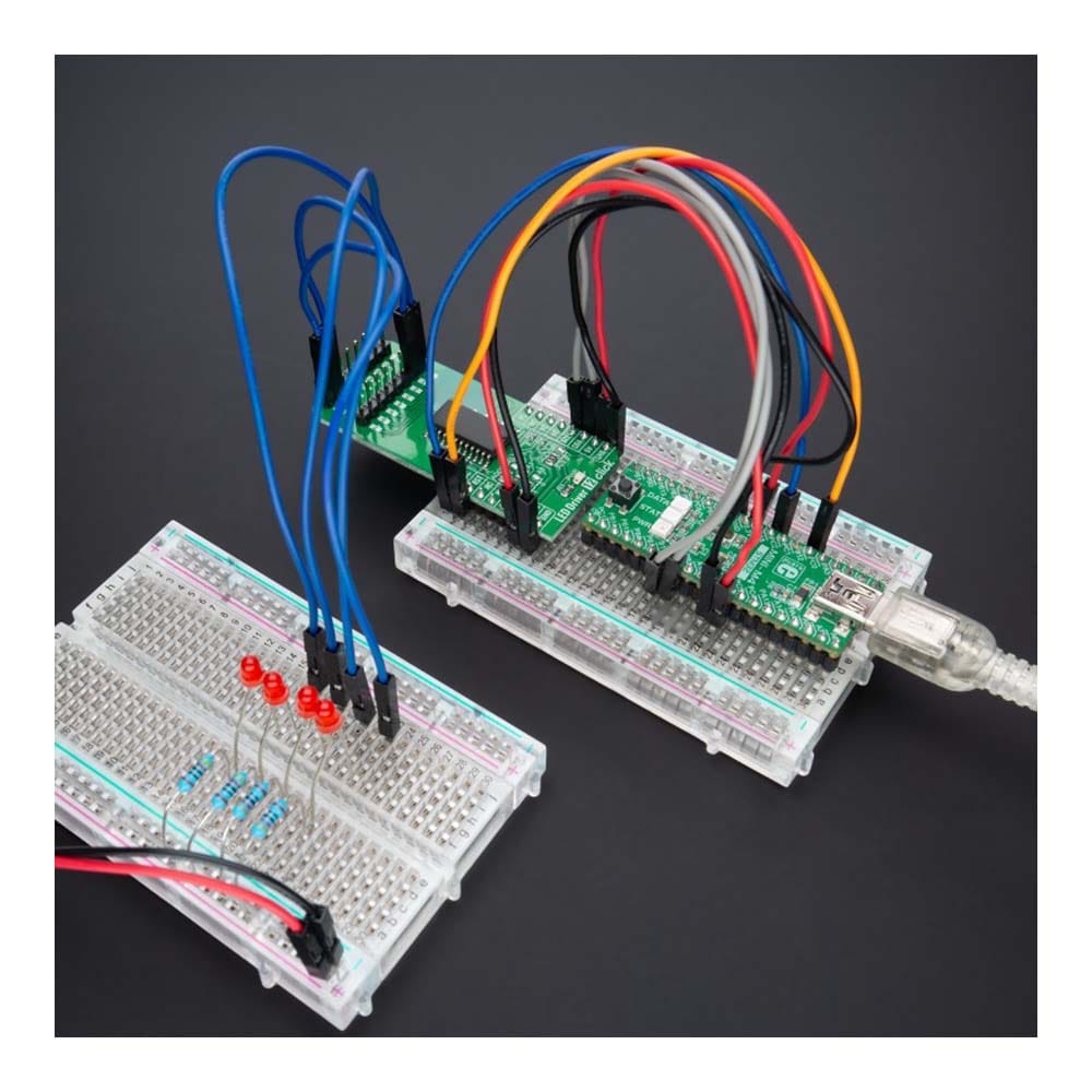
La carte LED Driver 12 Click Board™ est une carte complémentaire compacte qui simplifie le contrôle de plusieurs LED. Cette carte comprend le PCA9532, un extenseur d'E/S configurable I2C 16 bits optimisé pour la gradation des LED en 256 étapes discrètes Rouge/Vert/Bleu (RVB) de NXP Semiconductors. Le PCA9532 offre une efficacité élevée, prenant en charge jusqu'à 16 canaux LED et délivrant un maximum de 25 mA de courant LED par canal. Il contient un oscillateur interne avec deux taux de clignotement programmables par l'utilisateur et des cycles de service couplés à la sortie PWM. Tous les bits non utilisés pour contrôler les LED peuvent être utilisés pour l'extension GPIO, ce qui fournit une solution simple lorsque des E/S supplémentaires sont nécessaires pour certains capteurs, boutons-poussoirs ou surveillance d'alarme. Cette carte Click™ convient au mélange de couleurs et aux applications de rétroéclairage pour les produits de divertissement, la signalisation d'état des LED, les projets domotiques et bien d'autres.
Le LED Driver 12 Click Board™ est pris en charge par une bibliothèque compatible mikroSDK, qui comprend des fonctions qui simplifient le développement logiciel. Ce Click board™ est un produit entièrement testé, prêt à être utilisé sur un système équipé de la prise mikroBUS™.
How Does The LED Driver 12 Click Board™ Work?
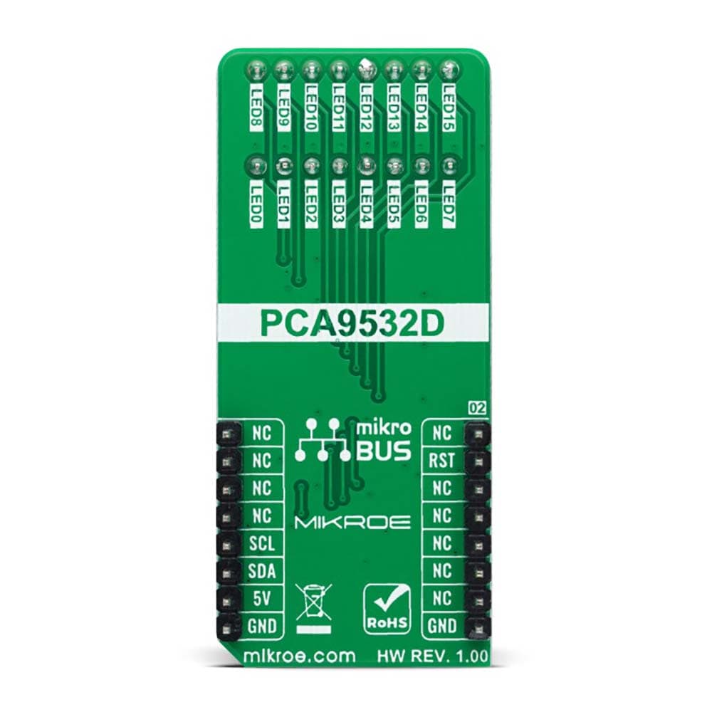
The LED Driver 12 Click Board™ as its foundation uses the PCA9532, a 16-bit I2C-configurable LED dimmer from NXP Semiconductors. The PCA9532 has two fully programmable PWM controllers used to control up to 16 LED channels, switching each of the LEDs ON and OFF independently. Each LED output, 16 LED drivers presented on two 1x8 male headers, with a maximum output current of 25mA per channel, has a programmable period ranging from 0.6Hz to 152Hz and a programmable duty cycle from 0 to 100%, which means that the LEDs can be set to blink steadily and visibly, or dimmed.
Any bits not used for controlling the LED channels can be used for General Purpose parallel Input/Output (GPIO) expansion, providing a simple solution when additional I/O is needed for some power switches, sensors, push-buttons, alarm monitoring, fans, or other applications.
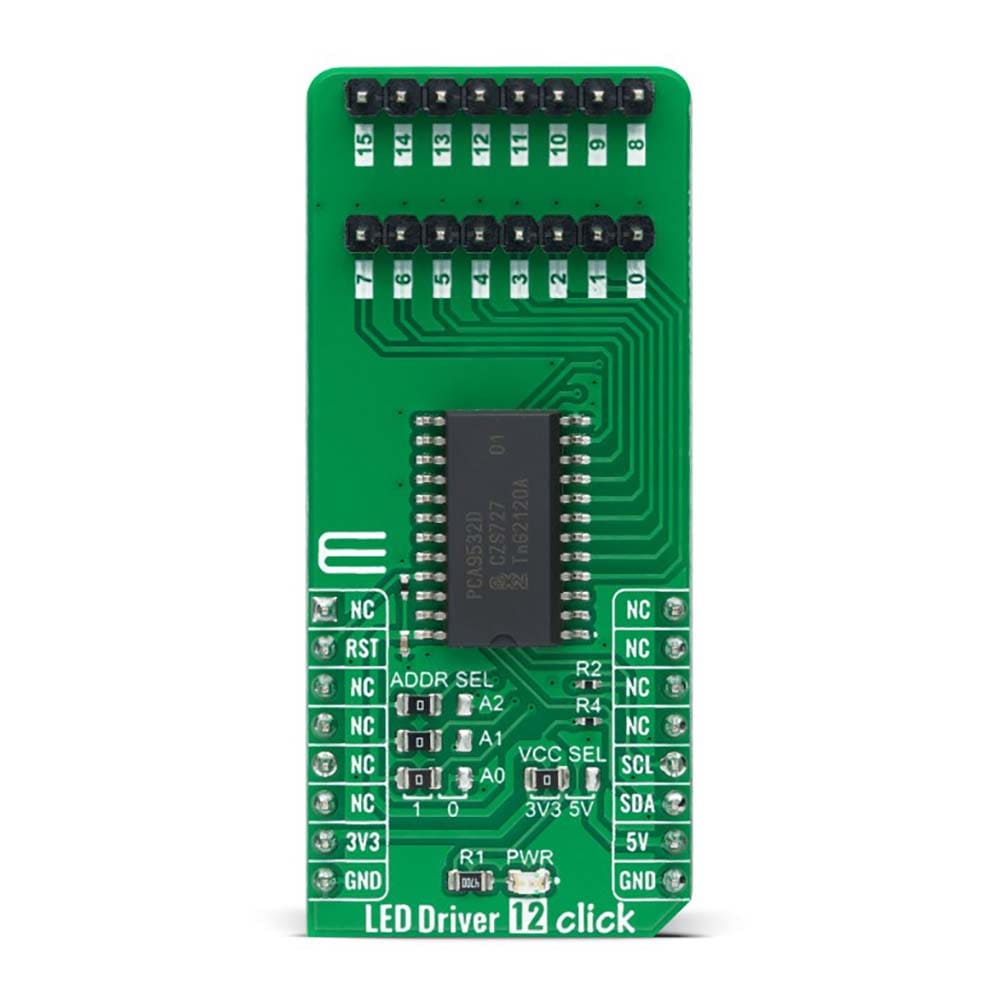
The LED Driver 12 Click Board™ communicates with MCU using the standard I2C 2-Wire interface that supports Standard-Mode (100 kHz) and Fast-Mode (400 kHz) operation. The PCA9532 has a 7-bit slave address with the first five MSBs fixed to 1100. The address pins A0, A1, and A2, are programmed by the user and determine the value of the last three LSBs of the slave address, which can be selected by onboard SMD jumpers labelled as ADDR SEL allowing selection of the slave address LSBs.
Alongside the internal Power-On Reset (POR) function, this board also has an active-low reset signal routed on the RST pin of the mikroBUS™ socket used to recover from a bus-fault condition. When this signal is asserted low, the PCA9532 resets its registers alongside with I2C state machine and deselects all channels.
The LED Driver 12 Click Board™ can operate with both 3.3V and 5V logic voltage levels selected via the VCC SEL jumper. This way, it is allowed for both 3.3V and 5V capable MCUs to use the communication lines properly. However, the Click board™ comes equipped with a library containing easy-to-use functions and an example code that can be used, as a reference, for further development.
SPECIFICATIONS
| Type | LED Drivers |
| Applications | The LED Driver 12 Click Board™ can be used for color mixing and backlight application for amusement products, LED status signalization, home automation projects, and many more |
| On-board modules | PCA9532 - 16-bit I2C-configurable LED dimmer from NXP Semiconductors |
| Key Features | Low power consumption, 16 channels, ON/OFF LED channels control, two selectable fully programmable blink rates, supports hot insertion, drive LEDs to 25mA, and more |
| Interface | I2C |
| Compatibility | mikroBUS |
| Click board size | L (57.15 x 25.4 mm) |
| Input Voltage | 3.3V or 5V |
PINOUT DIAGRAM
This table shows how the pinout of the LED Driver 12 Click Board™ corresponds to the pinout on the mikroBUS™ socket (the latter shown in the two middle columns).
| Notes | Pin | Pin | Notes | ||||
|---|---|---|---|---|---|---|---|
| NC | 1 | AN | PWM | 16 | NC | ||
| Reset | RST | 2 | RST | INT | 15 | NC | |
| NC | 3 | CS | RX | 14 | NC | ||
| NC | 4 | SCK | TX | 13 | NC | ||
| NC | 5 | MISO | SCL | 12 | SCL | I2C Clock | |
| NC | 6 | MOSI | SDA | 11 | SDA | I2C Data | |
| Power Supply | 3.3V | 7 | 3.3V | 5V | 10 | 5V | Power Supply |
| Ground | GND | 8 | GND | GND | 9 | GND | Ground |
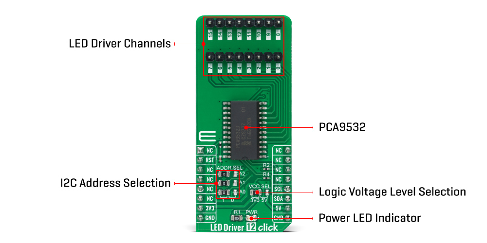
ONBOARD SETTINGS AND INDICATORS
| Label | Name | Default | Description |
|---|---|---|---|
| LD1 | PWR | - | Power LED Indicator |
| JP1-JP3 | ADDR SEL | - | I2C Address Selection 1/0: Left position 1, Right position 0 |
| JP4 | VCC SEL | - | Logic Level Voltage Selection 3V3/5V: Left position 3V3, Right position 5V |
| J1-J2 | 0-15 | - | LED Driver Channels |
LED DRIVER 12 CLICK ELECTRICAL SPECIFICATIONS
| Description | Min | Typ | Max | Unit |
|---|---|---|---|---|
| Supply Voltage | 3.3 | - | 5 | V |
| Maximum Output Current | - | - | 25 | mA |
| Operating Temperature Range | -40 | +25 | +85 | °C |
Software Support
We provide a library for the LED Driver 12 Click Board™ as well as a demo application (example), developed using MikroElektronika compilers. The demo can run on all the main MikroElektronika development boards.
The package can be downloaded/installed directly from NECTO Studio The package Manager (recommended), downloaded from our LibStock™ or found on MikroE Github account.
Library Description
This library contains API for the LED Driver 12 Click Board™ driver.
Key functions
-
leddriver12_set_led_configThis function sets the specified LED config. -
leddriver12_set_led_port_configThis function sets the specified LED port config. -
leddriver12_set_blink_period_pwm_0This function sets the blink period of PWM 0 function.
Example Description
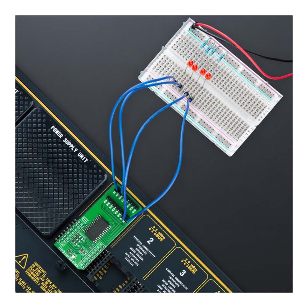
This example demonstrates the use of the LED Driver 12 Click Board™.
void application_task ( void )
 {
     leddriver12_set_led_port_config ( &leddriver12, LEDDRIVER12_LED0_TO_3, LEDDRIVER12_LED_ON );
     leddriver12_set_led_port_config ( &leddriver12, LEDDRIVER12_LED4_TO_7, LEDDRIVER12_LED_ON );
     log_printf ( &logger, " LEDs 0-7 turns ON rn" );
     Delay_ms( 2000 );
     leddriver12_set_led_port_config ( &leddriver12, LEDDRIVER12_LED0_TO_3, LEDDRIVER12_LED_OFF );
     leddriver12_set_led_port_config ( &leddriver12, LEDDRIVER12_LED4_TO_7, LEDDRIVER12_LED_OFF );
     log_printf ( &logger, " LEDs 0-7 turns OFF rnn" );
     Delay_ms( 2000 );
 }
The full application code, and ready to use projects can be installed directly from NECTO Studio The package Manager (recommended), downloaded from our LibStock™ or found on MikroE Github account.
Other MikroE Libraries used in the example:
- MikroSDK.Board
- MikroSDK.Log
- Click.LEDDriver12
Additional Notes and Information
Depending on the development board you are using, you may need USB UART click, USB UART 2 Click or RS232 Click to connect to your PC, for development systems with no UART to USB interface available on the board. UART terminal is available in all MikroElektronika compilers.
MIKROSDK
The LED Driver 12 Click Board™ is supported with mikroSDK - MikroElektronika Software Development Kit. To ensure proper operation of mikroSDK compliant Click board™ demo applications, mikroSDK should be downloaded from the LibStock and installed for the compiler you are using.
Carte de pilote LED 12 Click
Frequently Asked Questions
Have a Question?
Be the first to ask a question about this.