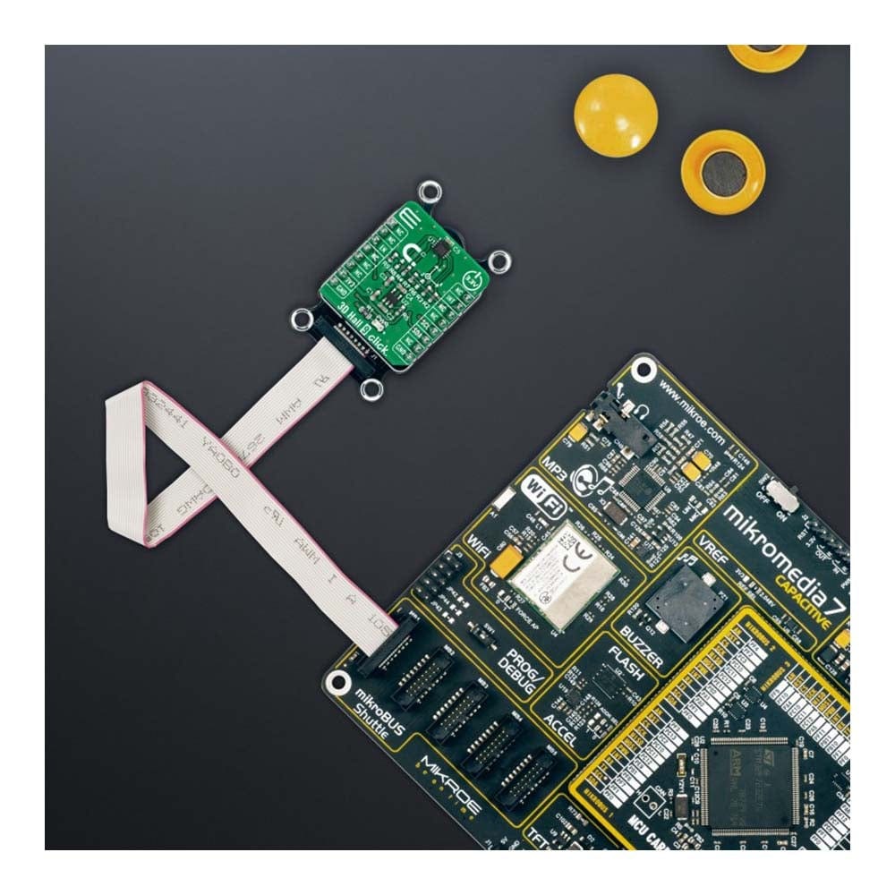
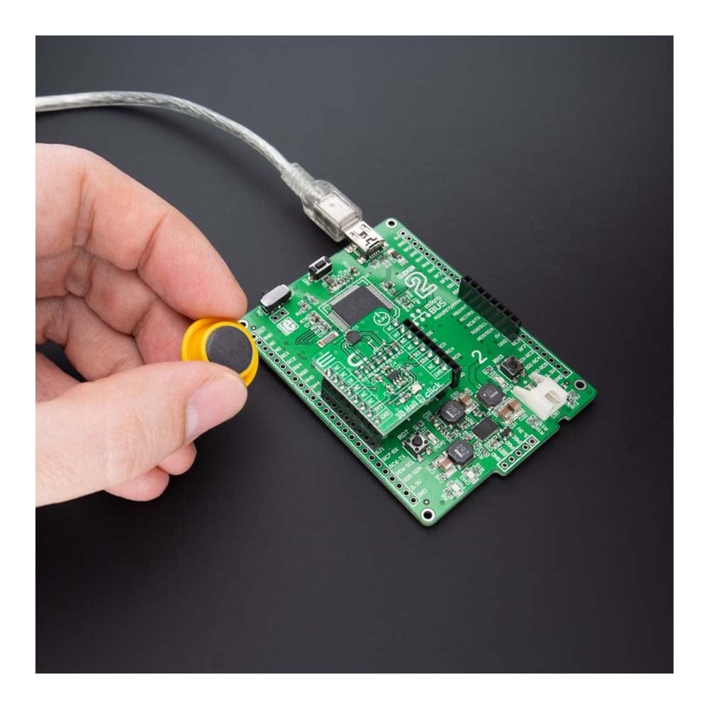
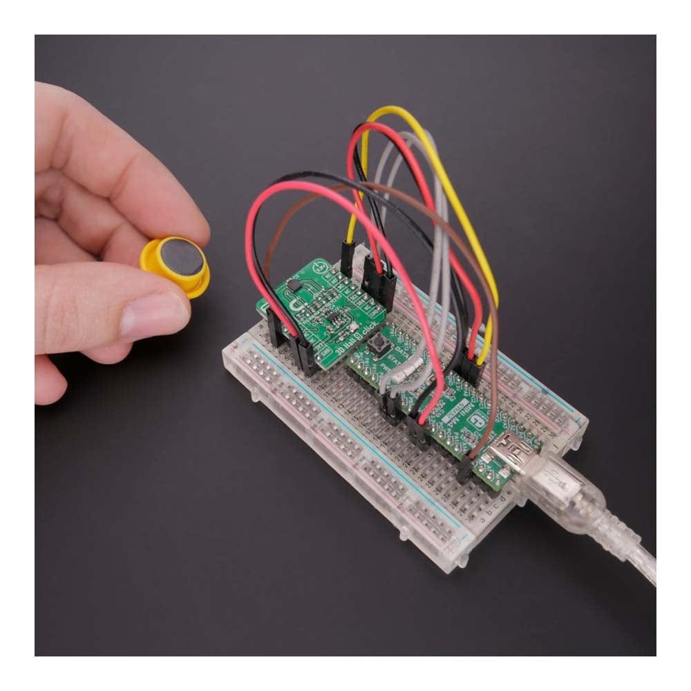
Tableau à cliquer 3D Hall 9
Key Features
- Faible consommation d'énergie, sensibilité réglée en usine à 1 % de précision ± 500 G, capteur de température intégré, interface I2C avec adresses esclaves sélectionnables, et plus encore
- Basé sur le capteur à effet Hall linéaire 3D ALS31300 utilisé pour détecter la force d'un champ magnétique dans les trois dimensions (axes X, Y et Z) d'Allegro Microsystems
- Peut être utilisé pour diverses applications, telles que la détection 3D pour le mouvement linéaire frontal, la détection de position par glissement et les mesures d'angle de rotation
- mikroBUS : interface I2C
Overview
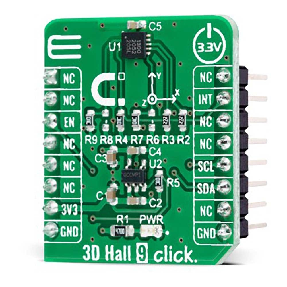
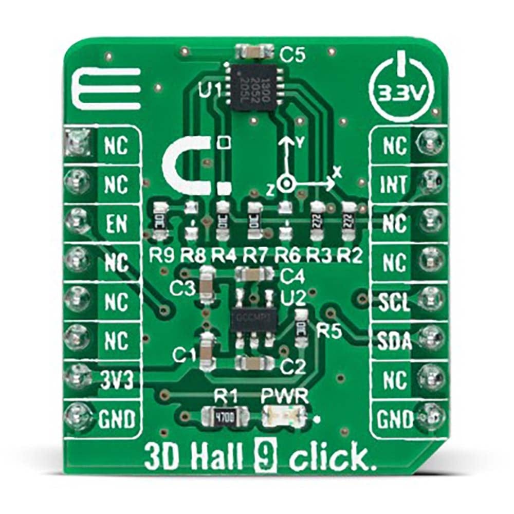
La carte 3D Hall 9 Click Board™ est une carte complémentaire compacte utilisée pour détecter la force d'un champ magnétique dans les trois dimensions. Cette carte comprend l'ALS31300, un capteur à effet Hall linéaire 3D avec sortie numérique et gestion avancée de faible consommation d'Allegro Microsystems. L'ALS31300 dispose d'une interface I2C, ce qui lui permet d'être facilement configuré par MCU avec les données de mesure fournies au format numérique de 12 bits correspondant au champ magnétique mesuré dans chaque axe X, Y et Z. Il offre également la possibilité de définir différentes adresses esclaves I2C (16 adresses uniques) en renseignant les résistances appropriées souhaitées par l'utilisateur. La gestion de l'alimentation de l'ALS31300 est hautement configurable, ce qui permet une optimisation du courant d'alimentation et des performances au niveau du système.
Le 3D Hall 9 Click Board™ convient à diverses applications, telles que la détection 3D pour le mouvement linéaire frontal, la détection de position par glissement et les mesures d'angle de rotation.
How Does The 3D Hall 9 Click Board™ Work?
The 3D Hall 9 Click Board™ as its foundation uses the ALS31300, a 3D linear Hall-effect sensor used to detect the strength of a magnetic field in all three dimensions (X, Y, and Z axes) from Allegro Microsystems. The ALS31300 provides a 12-bit digital output value proportional to the magnetic field generally applied to any of the Hall elements, alongside a 12-bit temperature output representing the junction temperature of the IC. The quiescent output value (zero magnetic fields used) is at mid-scale. The ALS31300 comes with the factory-programmed sensitivity range of ±500G, suitable for 3D linear sensing or 2D angle sensing applications.
Power management on the ALS31300 is user-selectable and highly configurable, allowing for system-level optimization of current consumption and performance. It supports three different power modes: Active Mode, Sleep Mode, and Low-Power Duty Cycle Mode (LPDCM). The operating mode of the ALS31300 will be determined by the selected proper value of the 0x27 register. More information on the operational modes can be found in the attached datasheet.
The 3D Hall 9 Click Board™ communicates with MCU using the standard I2C 2-Wire interface to read data and configure settings, supporting Standard Mode operation with a clock frequency of 100kHz and Fast Mode up to 400kHz. It provides data in digital format of 12-bits corresponding to the magnetic field measured in each X, Y, and Z axes. The ALS31300 also requires a supply voltage of 3V to work regularly. Therefore, a small LDO regulator, NCP170 from ON Semiconductor, provides 3V out of mikroBUS™ 3V3 power rail. This Click board™ also uses the Enable pin labelled as EN and routed to the CS pin of the mikroBUS™ socket to optimize power consumption, used for its power ON/OFF purposes.
The ALS31300 provides the ability to set different I2C slave addresses (16 unique addresses) by populating the appropriate resistors (R8 and R6), thus forming a voltage divider with a voltage value that corresponds to the desired I2C address. It also possesses an additional interrupt signal, routed on the INT pin of the mikroBUS™ socket labelled as INT, which integrates detection and reporting of significant changes in an applied magnetic field (independently enabled or disabled for each of the three axes). An interrupt event is initiated when the applied magnetic field forces the ADC output to a value greater than or equal to the user-programmed threshold.
The 3D Hall 9 Click Board™ can be operated only with a 3.3V logic voltage level. The board must perform appropriate logic voltage level conversion before using MCUs with different logic levels. However, the Click board™ comes equipped with a library containing functions and an example code that can be used, as a reference, for further development.
SPECIFICATIONS
Type | Magnetic |
Applications | The 3D Hall 9 Click Board™ be used for various applications, such as 3D sensing for head-on linear motion, slide-by position sensing, and rotation angle measurements |
On-board modules | ALS31300 - 3D linear Hall-effect sensor used to detect the strength of a magnetic field in all three dimensions (X, Y, and Z axes) from Allegro Microsystems |
Key Features | Low power consumption, 1% accurate factory-trimmed sensitivity ±500 G, integrated temperature sensor, I2C interface with selectable slave addresses, and more |
Interface | I2C |
Compatibility | mikroBUS |
Click board size | S (28.6 x 25.4 mm) |
Input Voltage | 3.3V |
PINOUT DIAGRAM
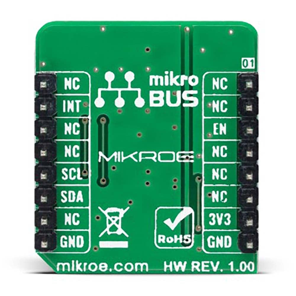
This table shows how the pinout of the 3D Hall 9 Click Board™ corresponds to the pinout on the mikroBUS™ socket (the latter shown in the two middle columns).
Notes | Pin | Pin | Notes | ||||
---|---|---|---|---|---|---|---|
NC | 1 | AN | PWM | 16 | NC | ||
NC | 2 | RST | INT | 15 | INT | Interrupt | |
Enable | EN | 3 | CS | RX | 14 | NC | |
NC | 4 | SCK | TX | 13 | NC | ||
NC | 5 | MISO | SCL | 12 | SCL | I2C Clock | |
NC | 6 | MOSI | SDA | 11 | SDA | I2C Data | |
Power Supply | 3.3V | 7 | 3.3V | 5V | 10 | NC | |
Ground | GND | 8 | GND | GND | 9 | GND | Ground |
ONBOARD SETTINGS AND INDICATORS
Label | Name | Default | Description |
---|---|---|---|
LD1 | PWR | - | Power LED Indicator |
R6, R8 | R6, R8 | Unpopulated | I2C Address Selection Jumpers |
3D HALL 9 CLICK ELECTRICAL SPECIFICATIONS
Description | Min | Typ | Max | Unit |
---|---|---|---|---|
Supply Voltage | - | 3.3 | - | V |
Sensing Range | -500 | - | +500 | G |
Sensitivity | - | 4 | - | V |
Resolution | - | 12 | - | bit |
Operating Temperature Range | -40 | +25 | +85 | °:C |
We provide a library for the 3D Hall 9 Click Board™ as well as a demo application (example), developed using MikroElektronika compilers. The demo can run on all the main MikroElektronika development boards.
The package can be downloaded/installed directly from NECTO Studio The package Manager (recommended), downloaded from our LibStock™ or found on Mikroe Github account.
Library Description
This library contains API for 3D Hall 9 Click driver.
Key functions
-
c3dhall9_write_register
This function writes a desired data to the selected register by using I2C serial interface. -
c3dhall9_read_register
This function reads a desired data from the selected register by using I2C serial interface. -
c3dhall9_read_data
This function reads new data which consists of X, Y, and Z axis values in Gauss, and temperature in Celsius. It also calculates the angles between all axes in Degrees based on the raw axes data read.
Example Description
This example demonstrates the use of the 3D Hall 9 Click Board™ by reading the magnetic flux density from 3 axes as well as the angles between axes and the sensor temperature.
void application_task ( void )
{
c3dhall9_data_t sensor_data;
if ( C3DHALL9_OK == c3dhall9_read_data ( &c3dhall9, &sensor_data ) )
{
log_printf( &logger, " X-axis: %.1f Gaussrn", sensor_data.x_axis );
log_printf( &logger, " Y-axis: %.1f Gaussrn", sensor_data.y_axis );
log_printf( &logger, " Z-axis: %.1f Gaussrn", sensor_data.z_axis );
log_printf( &logger, " Angle XY: %.1f Degreesrn", sensor_data.angle_xy );
log_printf( &logger, " Angle XZ: %.1f Degreesrn", sensor_data.angle_xz );
log_printf( &logger, " Angle YZ: %.1f Degreesrn", sensor_data.angle_yz );
log_printf( &logger, " Temperature: %.2f Celsiusrnn", sensor_data.temperature );
Delay_ms ( 300 );
}
}
The full application code, and ready to use projects can be installed directly from NECTO Studio The package Manager (recommended), downloaded from our LibStock™ or found on Mikroe Github account.
Other Mikroe Libraries used in the example:
- MikroSDK.Board
- MikroSDK.Log
- Click.3DHall9
Additional Notes and Information
Depending on the development board you are using, you may need a USB UART Click, USB UART 2 Click or RS232 Click to connect to your PC, for development systems with no UART to USB interface available on the board. UART terminal is available in all MikroElektronika compilers.
MIKROSDK
The 3D Hall 9 Click Board™ is supported with mikroSDK - MikroElektronika Software Development Kit. To ensure proper operation of mikroSDK compliant Click board™ demo applications, mikroSDK should be downloaded from the LibStock and installed for the compiler you are using.
Frequently Asked Questions
Have a Question?
Be the first to ask a question about this.