


Mikroelektronika d.o.o.
Carte à clic H-Bridge Driver 2
Carte à clic H-Bridge Driver 2
SKU: MIKROE-4931
Impossible de charger la disponibilité du service de retrait


Overview
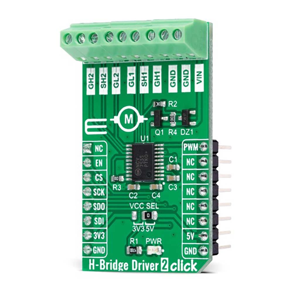
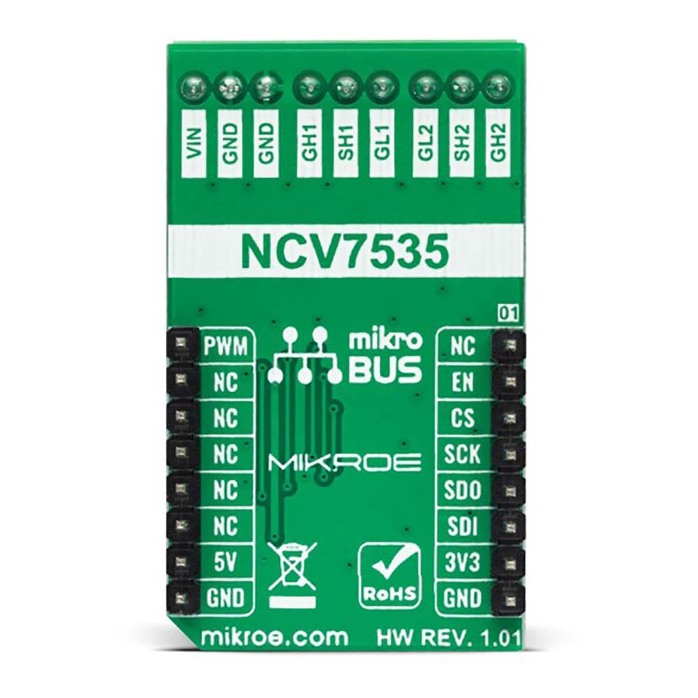
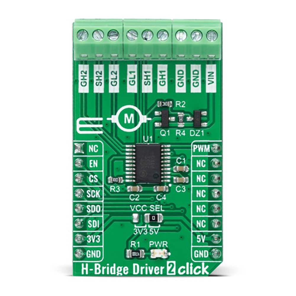
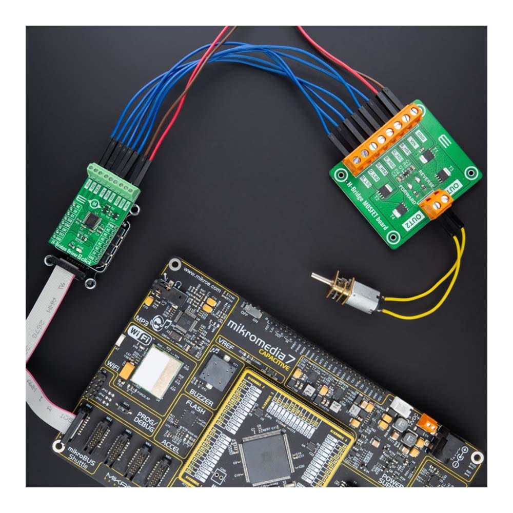
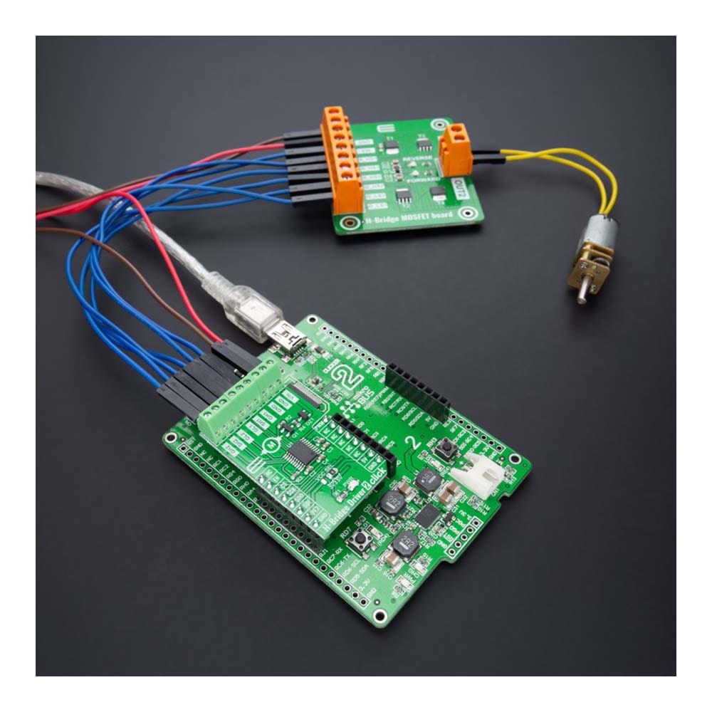
The H-Bridge Driver 2 Click Board™ is a compact add-on board that contains an H-bridge gate driver, also known as a full-bridge pre-driver. This board features the NCV7535, a monolithic H−bridge pre-driver for a DC motor with an enhanced feature set, useful in automotive systems from ON Semiconductor. The gate driver channels are independently controlled by a 24-bit SPI interface, allowing this Click board™ to be optionally configured in a single or dual H-bridge mode. It has a wide operating voltage range from 6V to 18V with built-in protection features against short-circuit, under/over voltage, overcurrent, and overtemperature conditions. This Click board™ is suitable to drive external MOSFETs, thus providing control of a DC-motor.
The H-Bridge Driver 2 Click Board™ is supported by a mikroSDK compliant library, which includes functions that simplify software development. This Click board™ comes as a fully tested product, ready to be used on a system equipped with the mikroBUS™ socket.
Downloads
Le H-Bridge Driver 2 Click Board™ est une carte complémentaire compacte qui contient un pilote de grille en pont en H, également connu sous le nom de pré-pilote en pont complet. Cette carte comprend le NCV7535, un pré-pilote monolithique en pont en H pour un moteur à courant continu avec un ensemble de fonctionnalités améliorées, utile dans les systèmes automobiles d'ON Semiconductor. Les canaux du pilote de grille sont contrôlés indépendamment par une interface SPI 24 bits, ce qui permet à cette carte Click™ d'être configurée en option en mode pont en H simple ou double. Elle dispose d'une large plage de tension de fonctionnement de 6 V à 18 V avec des fonctions de protection intégrées contre les courts-circuits, les sous-tensions/surtensions, les surintensités et les surchauffes. Cette carte Click™ est adaptée pour piloter des MOSFET externes, permettant ainsi le contrôle d'un moteur à courant continu.
La carte Click Board™ H-Bridge Driver 2 est prise en charge par une bibliothèque compatible mikroSDK, qui comprend des fonctions qui simplifient le développement logiciel. Cette carte Click Board™ est un produit entièrement testé, prêt à être utilisé sur un système équipé du socket mikroBUS™.
| General Information | |
|---|---|
Part Number (SKU) |
MIKROE-4931
|
Manufacturer |
|
| Physical and Mechanical | |
Weight |
0.02 kg
|
| Other | |
EAN |
8606027389573
|
Frequently Asked Questions
Have a Question?
Be the first to ask a question about this.