


Mikroelektronika d.o.o.
Carte à clic pour moteur à courant continu 21
Carte à clic pour moteur à courant continu 21
SKU: MIKROE-4877
Impossible de charger la disponibilité du service de retrait
Overview
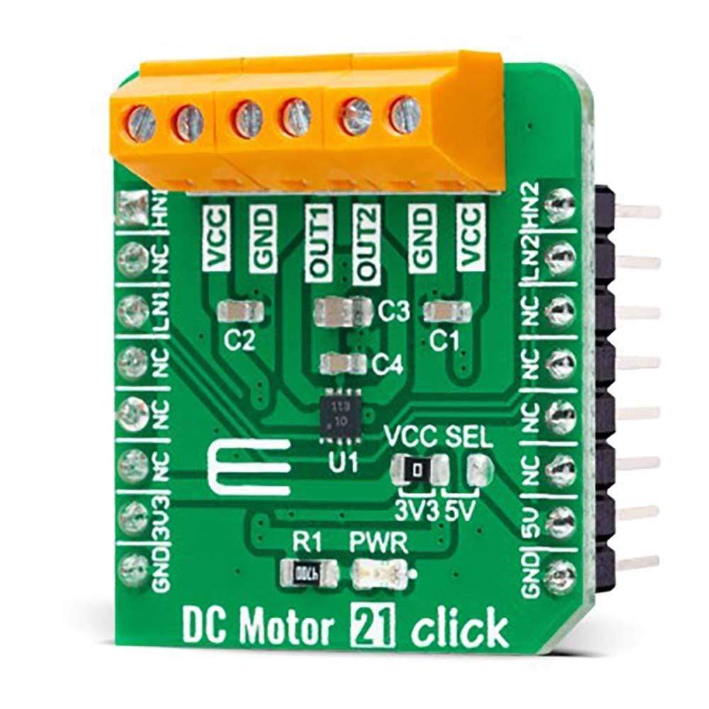
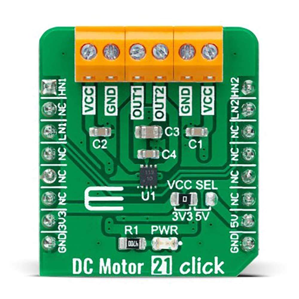
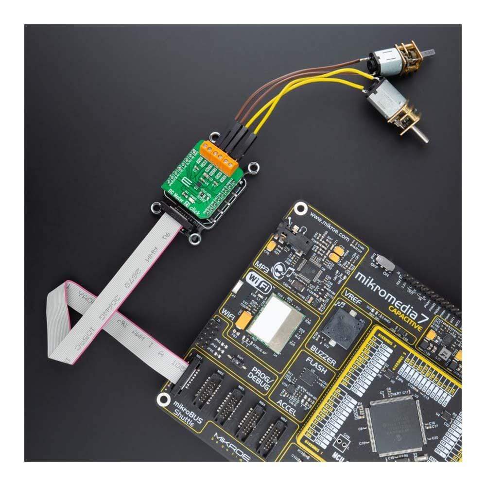
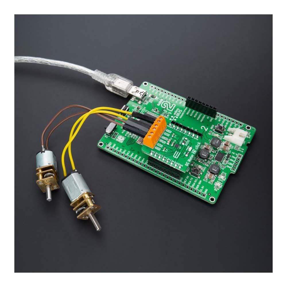
The DC Motor 21 Click Board™ is a compact add-on board that contains a brushed DC motor driver. This board features the A3910, a DC motor driver designed for low voltage power applications from Allegro Microsystems. It is controlled via several GPIO pins and has a wide operating voltage range with an output current capacity of 500mA. In addition to the possibility to be used in the full-bridge configuration to drive a single bidirectional DC motor, it can also be used as a dual half-bridge to drive dual DC motors. Using an integrated MOS switch improves braking action for the motor, compared to implementation with a simple clamp diode. Besides, it also features built-in protection such as crossover current protection and thermal shutdown.
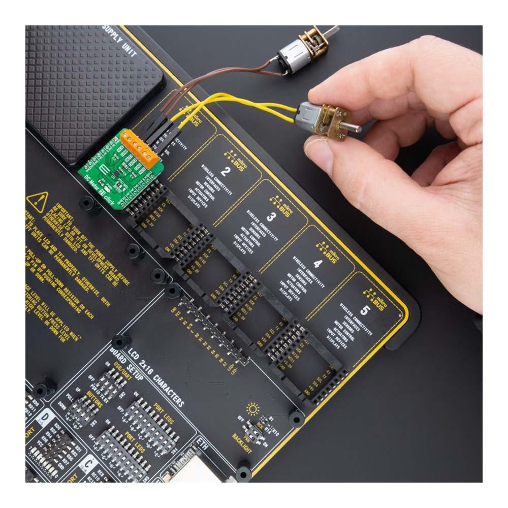
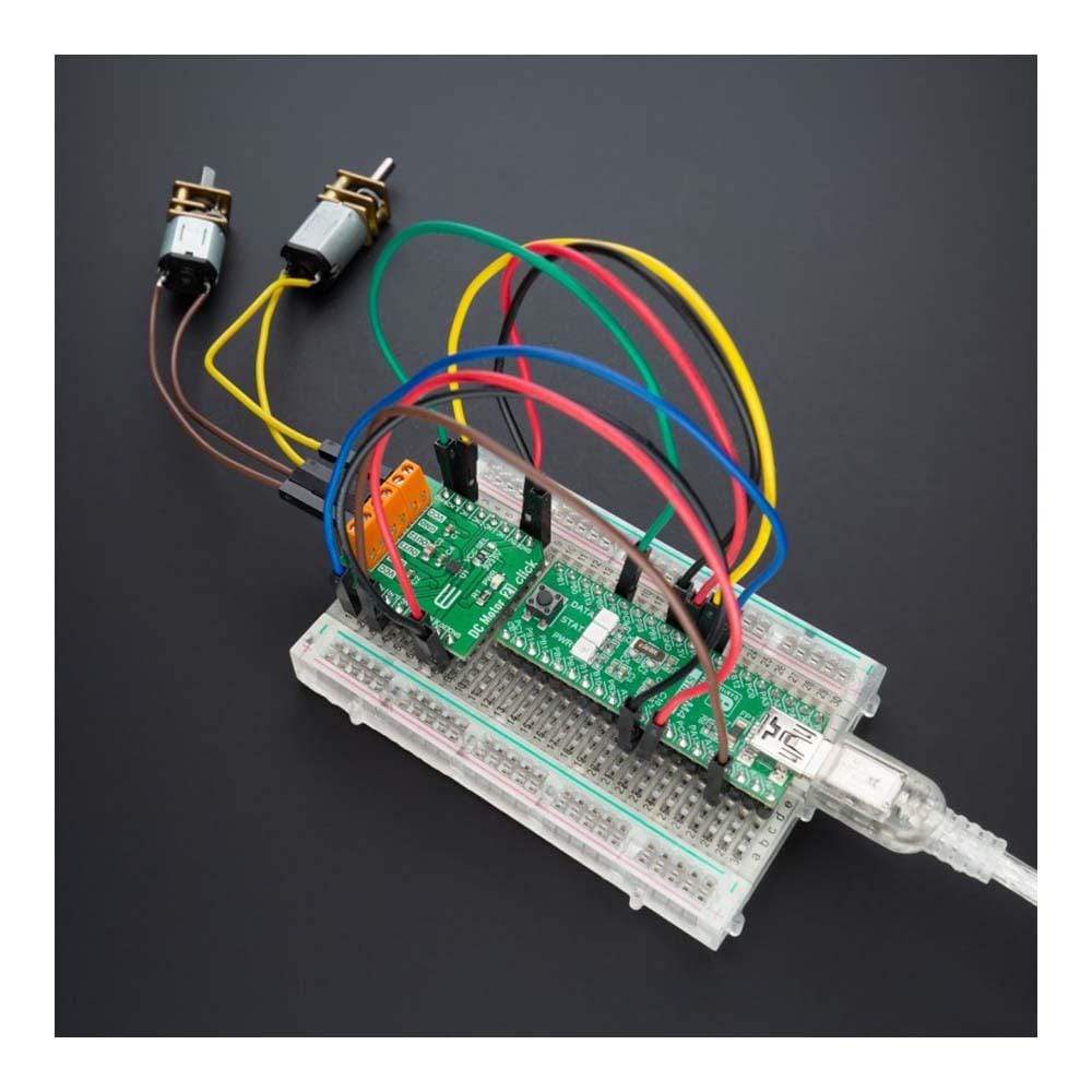
The DC Motor 21 Click Board™ is suitable for driving DC brushed motors and targeted at the consumer and industrial market with end applications to low voltage equipment.
Downloads
Le Moteur à courant continu 21 Click Board™ est une carte complémentaire compacte qui contient un pilote de moteur à courant continu à balais. Cette carte comprend l'A3910, un pilote de moteur à courant continu conçu pour les applications d'alimentation basse tension d'Allegro Microsystems. Il est contrôlé via plusieurs broches GPIO et dispose d'une large plage de tension de fonctionnement avec une capacité de courant de sortie de 500 mA. En plus de la possibilité d'être utilisé dans la configuration en pont complet pour piloter un seul moteur à courant continu bidirectionnel, il peut également être utilisé comme un double demi-pont pour piloter deux moteurs à courant continu. L'utilisation d'un commutateur MOS intégré améliore l'action de freinage du moteur, par rapport à la mise en œuvre avec une simple diode de serrage. En outre, il dispose également d'une protection intégrée telle qu'une protection contre les courants croisés et un arrêt thermique.
Le moteur à courant continu 21 Click Board™ est adapté à l'entraînement de moteurs à courant continu à balais et destiné au marché grand public et industriel avec des applications finales pour les équipements basse tension.
| General Information | |
|---|---|
Part Number (SKU) |
MIKROE-4877
|
Manufacturer |
|
| Physical and Mechanical | |
Weight |
0.02 kg
|
| Other | |
EAN |
8606027384219
|
Frequently Asked Questions
Have a Question?
Be the first to ask a question about this.