


Mikroelektronika d.o.o.
Carte à clic LP WiFi
Carte à clic LP WiFi
SKU: MIKROE-4836
Impossible de charger la disponibilité du service de retrait


Overview
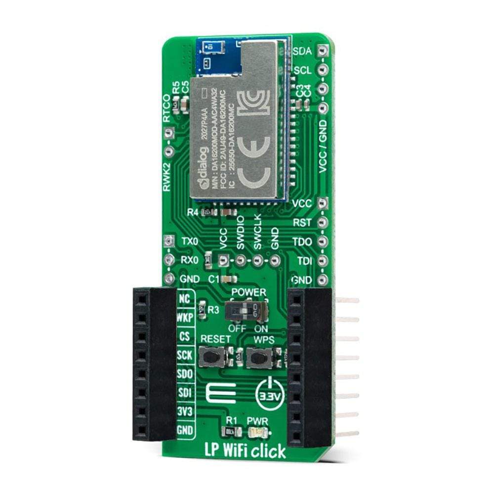
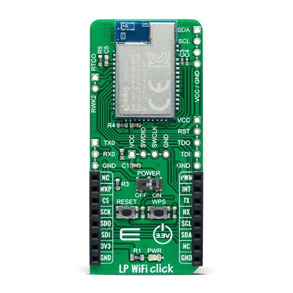
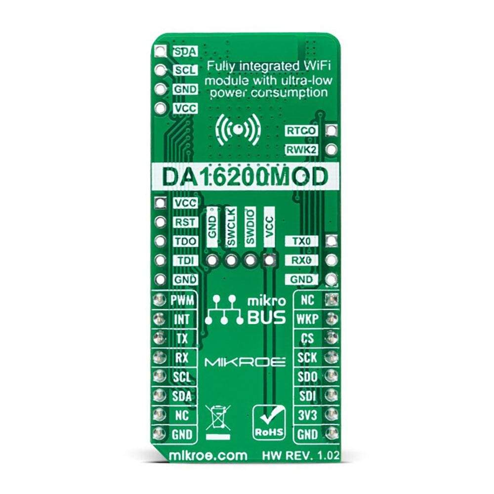
The LP WiFi Click Board™ is a compact add-on board that represents an ultra-low-power Wi-Fi solution. This board features the DA16200, a fully integrated Wi-Fi module with ultra-low power consumption, best RF performance, and a comfortable development environment from Dialog Semiconductor. In addition to the highly integrated ultra-low power Wi-Fi SoC, which is the basis of this module, it also includes a 40MHz crystal oscillator, 32.768kHz RTC clock, 4Mbyte flash memory, and chip antenna. Such low power operation can extend the battery life as long as a year or more, depending on the application. This Click Board™ is suitable for highly integrated and cost-effective IoT applications such as security systems, door locks, pet and asset trackers, sprinkler systems, connected lighting, wearables, and other IoT devices.
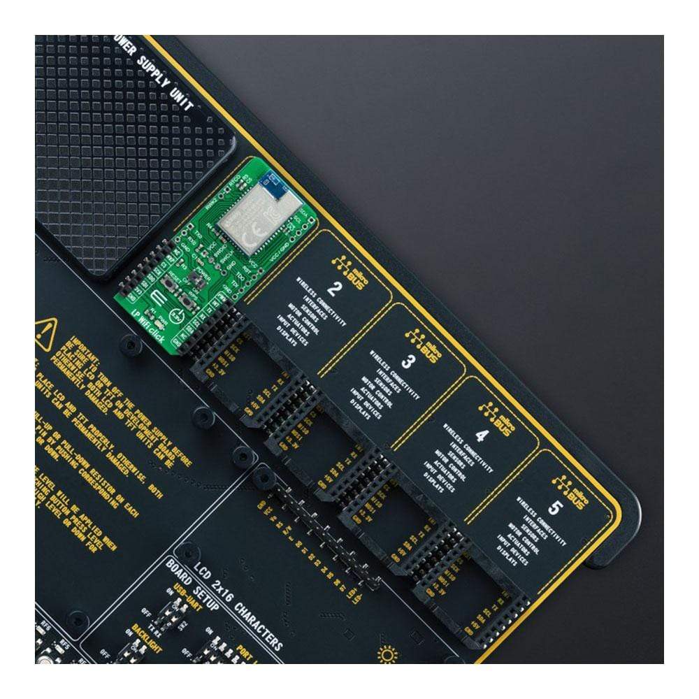
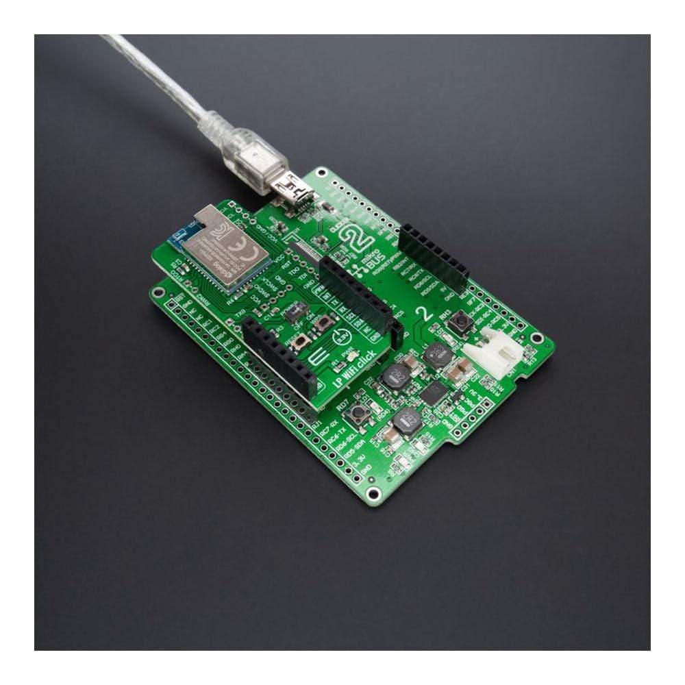
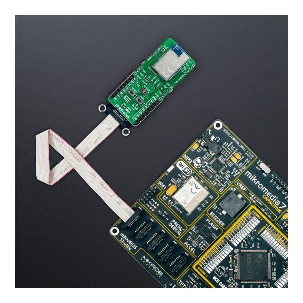
The LP WiFi Click Board™ is supported by a mikroSDK compliant library, which includes functions that simplify software development. This Click Board™ comes as a fully tested product, ready to be used on a system equipped with the mikroBUS™ socket.
Downloads
Le Carte Click Board LP Wi-Fi™ est une carte complémentaire compacte qui représente une solution Wi-Fi à très faible consommation d'énergie. Cette carte comprend le DA16200, un module Wi-Fi entièrement intégré avec une consommation d'énergie ultra-faible, les meilleures performances RF et un environnement de développement confortable de Dialog Semiconductor. En plus du SoC Wi-Fi à très faible consommation d'énergie hautement intégré, qui est la base de ce module, il comprend également un oscillateur à cristal de 40 MHz, une horloge RTC de 32,768 kHz, une mémoire flash de 4 Mo et une antenne à puce. Un tel fonctionnement à faible consommation d'énergie peut prolonger la durée de vie de la batterie jusqu'à un an ou plus, selon l'application. Cette Click Board™ convient aux applications IoT hautement intégrées et rentables telles que les systèmes de sécurité, les serrures de porte, les traceurs d'animaux et de biens, les systèmes d'arrosage, l'éclairage connecté, les appareils portables et autres appareils IoT.
Le LP WiFi Click Board™ est pris en charge par une bibliothèque compatible mikroSDK, qui comprend des fonctions qui simplifient le développement logiciel. Cette Click Board™ est un produit entièrement testé, prêt à être utilisé sur un système équipé du socket mikroBUS™.
| General Information | |
|---|---|
Part Number (SKU) |
MIKROE-4836
|
Manufacturer |
|
| Physical and Mechanical | |
Weight |
0.02 kg
|
| Other | |
EAN |
8606027383779
|
Frequently Asked Questions
Have a Question?
Be the first to ask a question about this.