


Mikroelektronika d.o.o.
Carte de clic pour moteur à courant continu 18
Carte de clic pour moteur à courant continu 18
SKU: MIKROE-4786
Impossible de charger la disponibilité du service de retrait
Overview
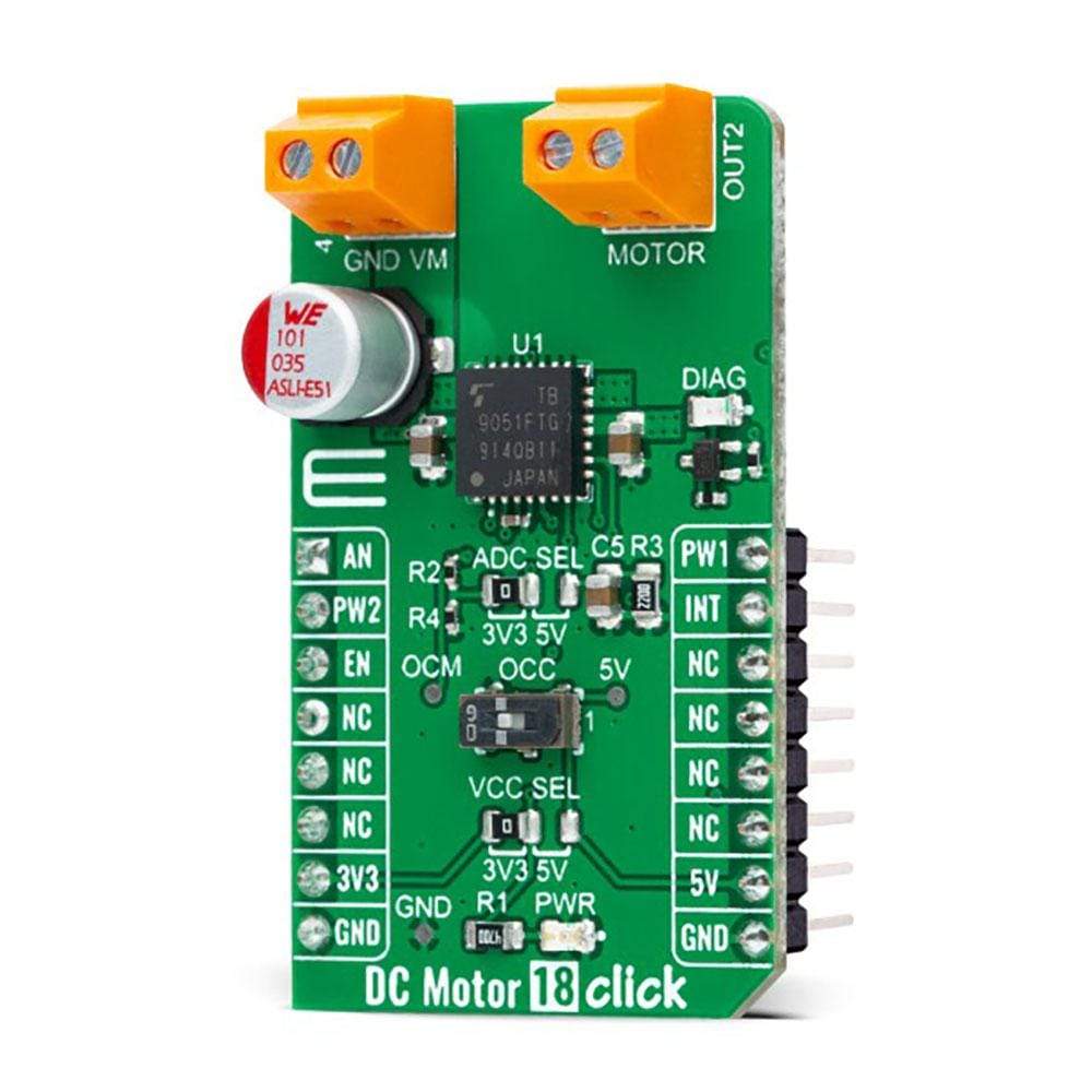
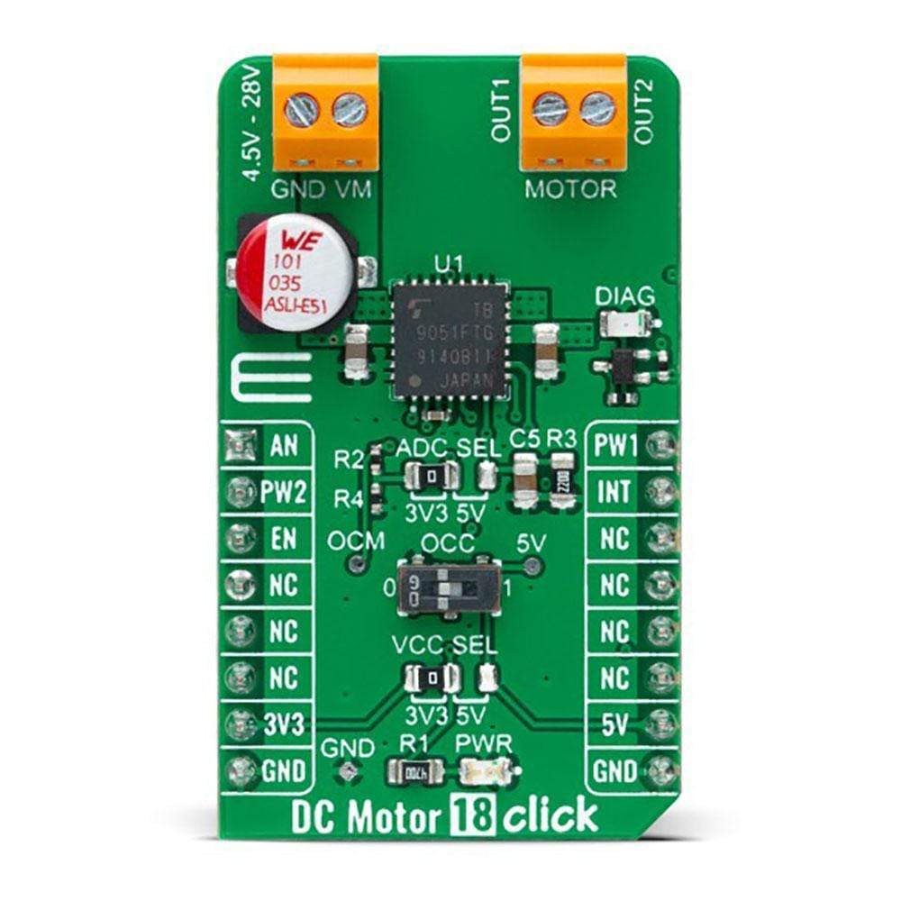
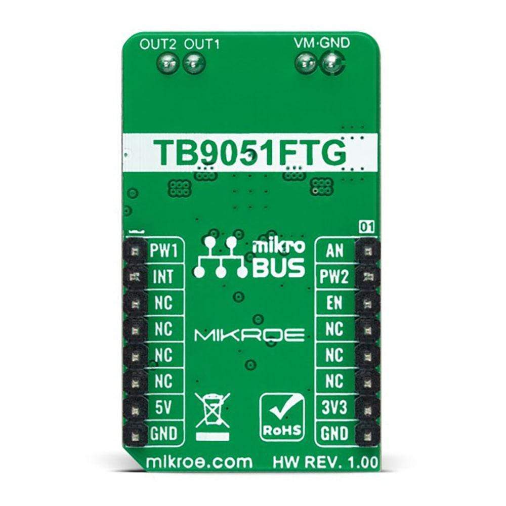
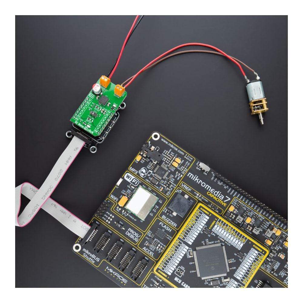
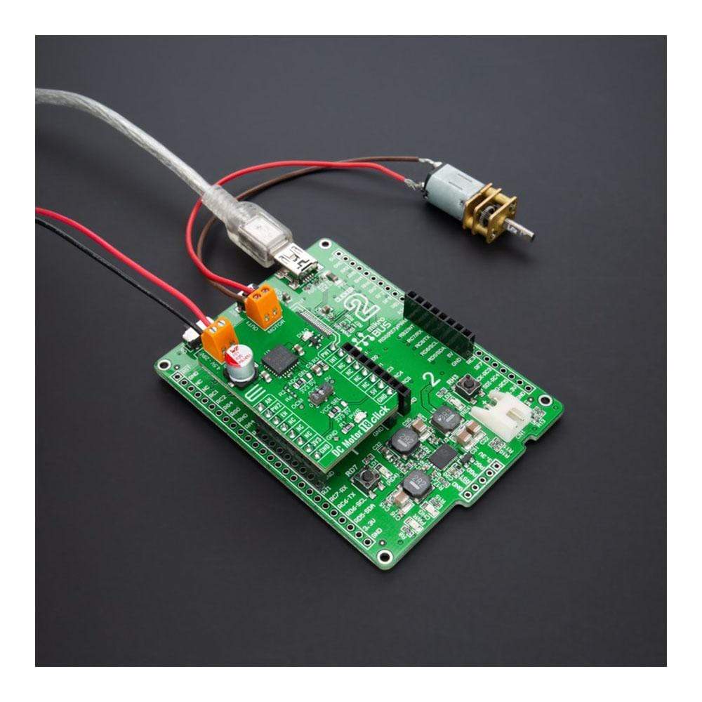
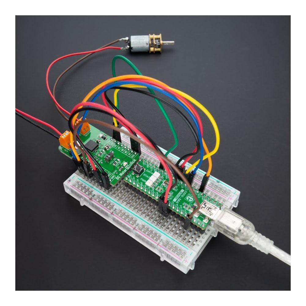
The DC Motor 18 Click Board™ is a compact add-on board that contains a brushed DC motor driver. This board features the TB9051FTG, an automotive PWM-type single-channel H-Bridge DC brushed motor driver from Toshiba Semiconductor. The Forward/Reverse/Brake mode can be selected according to PWM control signals, while the motor operation and stop mode can be chosen by an enable pin. It has a wide operating voltage range of 4.5V to 28V with an output current capacity of 5A max. Besides, it also features built-in protection against under-voltage, overcurrent, and overtemperature conditions. This Click Board™ is suitable for various automotive applications such as throttle and valve control, various engine bulbs, storing of door mirrors, and seat positioning.
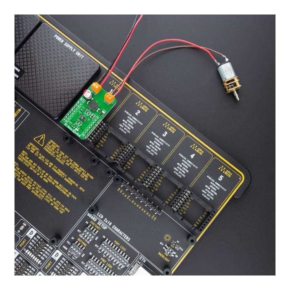
The DC Motor 18 Click Board™ is supported by a mikroSDK compliant library, which includes functions that simplify software development. This Click Board™ comes as a fully tested product, ready to be used on a system equipped with the mikroBUS™ socket.
Downloads
Le moteur à courant continu 18 Click Board™ est une carte complémentaire compacte qui contient un pilote de moteur à courant continu à balais. Cette carte comprend le TB9051FTG, un pilote de moteur à courant continu à balais à pont en H monocanal de type PWM pour automobile de Toshiba Semiconductor. Le mode marche avant/arrière/frein peut être sélectionné en fonction des signaux de commande PWM, tandis que le fonctionnement du moteur et le mode d'arrêt peuvent être choisis par une broche d'activation. Il dispose d'une large plage de tension de fonctionnement de 4,5 V à 28 V avec une capacité de courant de sortie de 5 A max. En outre, il dispose également d'une protection intégrée contre les conditions de sous-tension, de surintensité et de surchauffe. Ce Click Board™ convient à diverses applications automobiles telles que le contrôle de l'accélérateur et des soupapes, diverses ampoules de moteur, le stockage des rétroviseurs extérieurs et le positionnement des sièges.
Le Moteur à courant continu 18 Click Board™ est pris en charge par une bibliothèque compatible mikroSDK, qui comprend des fonctions qui simplifient le développement logiciel. Cette Click Board™ est un produit entièrement testé, prêt à être utilisé sur un système équipé du socket mikroBUS™.
| General Information | |
|---|---|
Part Number (SKU) |
MIKROE-4786
|
Manufacturer |
|
| Physical and Mechanical | |
Weight |
0.02 kg
|
| Other | |
EAN |
8606027383557
|
Frequently Asked Questions
Have a Question?
Be the first to ask a question about this.