Carte à clic LDC 2
Carte à clic LDC 2
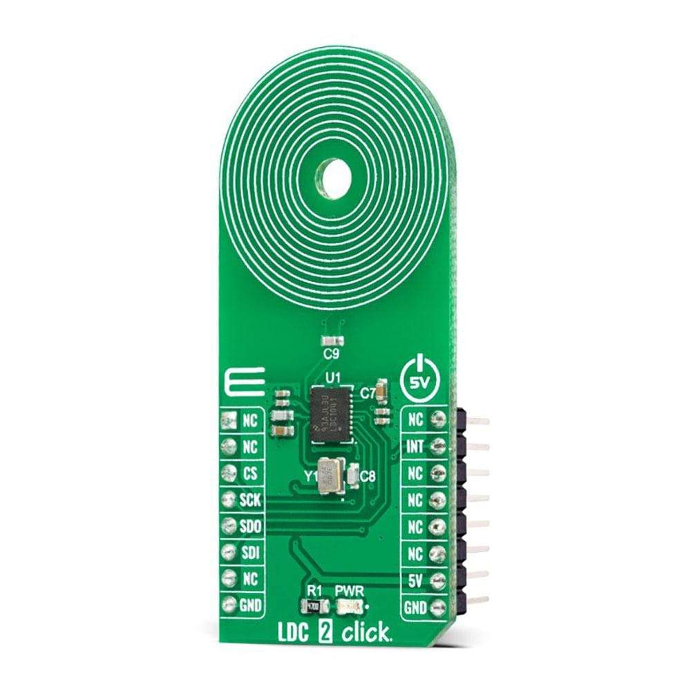
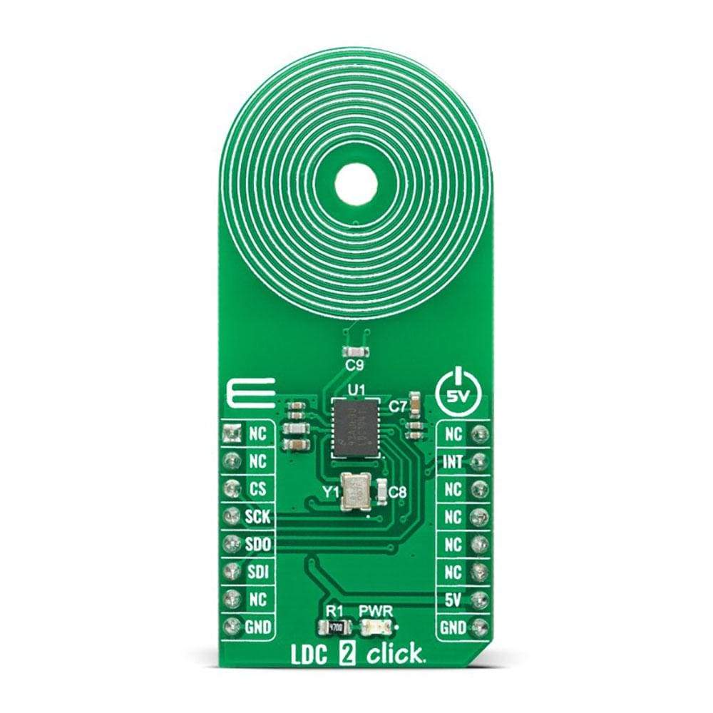
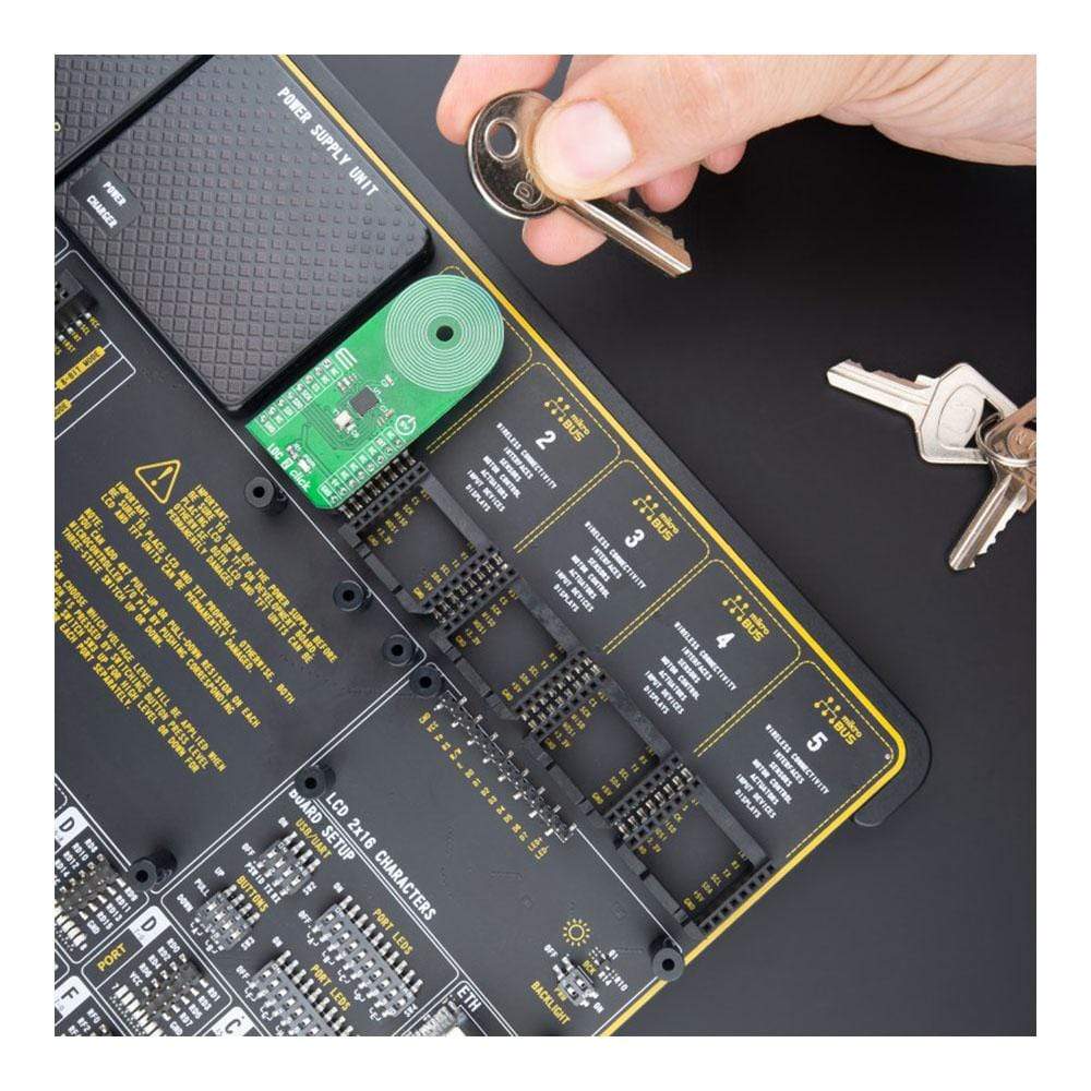
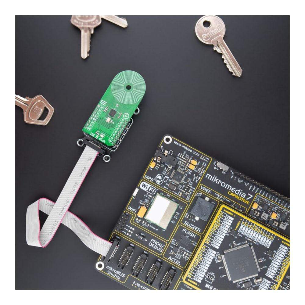
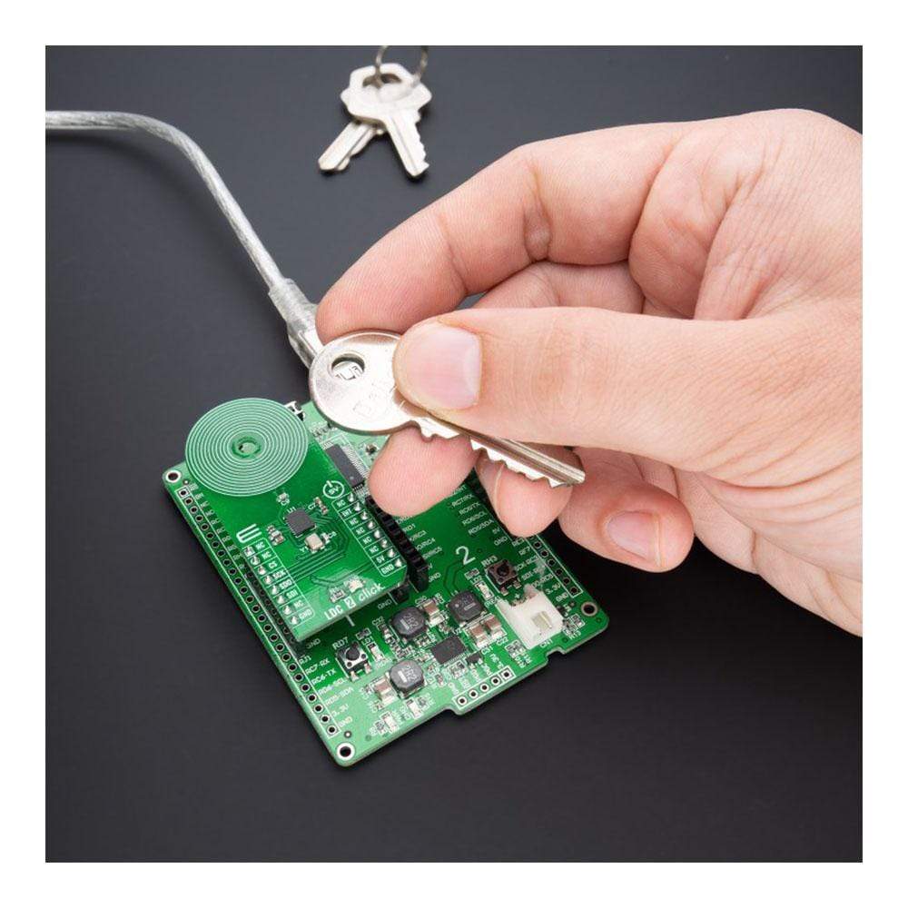
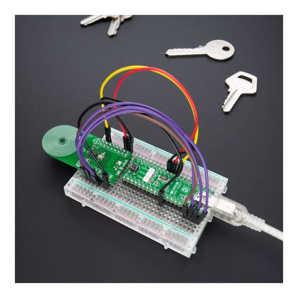
Le Carte à clic LDC 2™ est une carte complémentaire compacte qui mesure le changement d'inductance qu'une cible conductrice provoque lorsqu'elle se déplace dans le champ magnétique alternatif de l'inducteur. Cette carte comprend le LDC1041, un convertisseur inductance-numérique (LDC) pour les solutions de détection inductive de Texas Instruments. Cette Click Board™ est facile à utiliser, ne nécessitant que la fréquence du capteur entre 5 kHz et 5 MHz pour commencer la détection, et démontre l'utilisation de la technologie de détection inductive pour détecter et mesurer la présence, la position ou la composition d'un objet cible conducteur. Elle est livrée avec un exemple de bobine de capteur PCB conçue pour offrir à l'utilisateur une flexibilité maximale. Cette Click Board™ convient à la détection sans contact à courte portée qui permet une détection de position haute résolution et à faible coût des cibles conductrices, même dans des environnements difficiles.
La carte à clic LDC 2™ est pris en charge par une bibliothèque compatible mikroSDK, qui comprend des fonctions qui simplifient le développement logiciel. Cette Click Board™ est un produit entièrement testé, prêt à être utilisé sur un système équipé du socket mikroBUS™.
How Does The LDC 2 Click Board™ Work?
The LDC 2 Click Board™ as its foundation uses the LDC1041, an inductance-to-digital converter that simultaneously measures an LC resonator's impedance and resonant frequency from Texas Instruments. This Click board™ is easy-to-use, requiring only the sensor frequency within 5kHz and 5MHz to begin sensing, and demonstrates the use of inductive sensing technology to sense and measure a conductive target object's presence, position, or composition. In addition, the LDC1041 also measures the oscillation frequency of the LC circuit, used to determine the inductance of the LC circuit. The device then outputs a digital value that is inversely proportional to frequency.
The LDC measures the inductance change that a conductive target causes when it moves into the inductor's AC magnetic field to provide information about the target's position over a sensor coil. The inductance shift is caused by eddy currents (circulating currents) generated in the target due to the sensor's magnetic field. These eddy currents generate a secondary magnetic field that opposes the sensor field, causing a shift in the observed inductance, used for precise positioning of the target as it moves laterally over the sensor coil.
Also, the LDC1041 has two power modes: Active and Standby Mode. In Active Mode, the proximity data and frequency data conversion are enabled, while Standby mode represents the default mode on devices' Power-Up sequence. In Standby Mode, the conversion process is disabled. This Click board™ comes with an example of a PCB sensor coil designed to provide the user with maximum flexibility.
The LDC1041 communicates with MCU using the standard SPI serial interface with a maximum frequency of 4MHz. In addition to this serial interface, one GPIO pin connected to the mikroBUS™ socket is also used. The configurable interrupt pin, routed to the INT pin of the mikroBUS™ socket, may be configured in three different ways by programming the interrupt Terminal mode register with SPI. An interrupt pin provides the ability to act as a proximity switch, as a wake-up feature, or as a data-ready pin indicating a valid condition for new data availability.
The LDC 2 Click Board™ operates only with a 5V logic voltage level. The board must perform appropriate logic voltage level conversion before use with MCUs with different logic levels. However, the Click board™ comes equipped with a library containing functions and an example code that can be used, as a reference, for further development.
Specifications
Type | Inductance |
Applications | Can be used for contactless, short-range sensing that enables high-resolution and low-cost position sensing of conductive targets, even in harsh environments. |
On-board modules | LDC1041 - inductance-to-digital converter that simultaneously measures an LC resonator's impedance and resonant frequency from Texas Instruments |
Key Features | Low power consumption, short-range sensing technology, high durability, high flexibility, supports a wide frequency range from 5kHz to 5MHz, high performance, reliability, and more |
Interface | SPI |
Compatibility | mikroBUS |
Click board size | L (57.15 x 25.4 mm) |
Input Voltage | 5V |
Pinout diagram
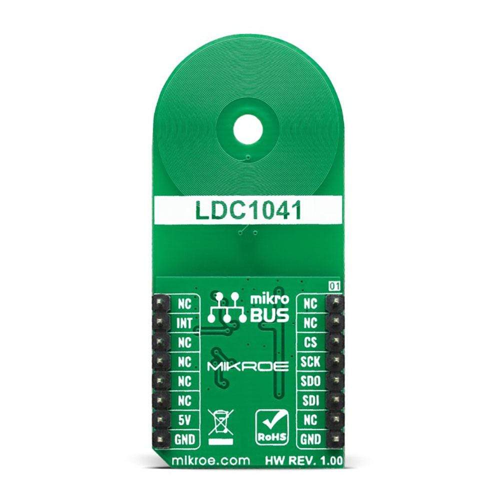
This table shows how the pinout on the LDC 2 Click Board™corresponds to the pinout on the mikroBUS™ socket (the latter shown in the two middle columns).
Notes | Pin | Pin | Notes | ||||
---|---|---|---|---|---|---|---|
NC | 1 | AN | PWM | 16 | NC | ||
NC | 2 | RST | INT | 15 | INT | Interrupt | |
SPI Chip Select | CS | 3 | CS | RX | 14 | NC | |
SPI Clock | SCK | 4 | SCK | TX | 13 | NC | |
SPI Data OUT | SDO | 5 | MISO | SCL | 12 | NC | |
SPI Data IN | SDI | 6 | MOSI | SDA | 11 | NC | |
NC | 7 | 3.3V | 5V | 10 | 5V | Power Supply | |
Ground | GND | 8 | GND | GND | 9 | GND | Ground |
Onboard settings and indicators
Label | Name | Default | Description |
---|---|---|---|
LD1 | PWR | - | Power LED Indicator |
LDC 2 Click electrical specifications
Description | Min | Typ | Max | Unit |
---|---|---|---|---|
Supply Voltage | - | 5 | - | V |
Sensor Frequency | 5 | - | 5000 | kHz |
Inductance Measurement Resolution | - | 24 | - | bits |
Operating Temperature Range | -40 | +25 | +125 | °C |
Software Support
We provide a library for the LDC 2 Click as well as a demo application (example), developed using MikroElektronika compilers. The demo can run on all the main MikroElektronika development boards.
The package can be downloaded/installed directly from NECTO Studio Package Manager(recommended way), downloaded from our LibStock™ or found on Mikroe GitHub account.
Library Description
This library contains an API for the LDC 2 Click Board™ driver.
Key Functions
ldc2_cfg_setup
- Config Object Initialization function.ldc2_init
- Initialization function.ldc2_default_cfg
- Click the Default Configuration function.
Example Description
This example demonstrates the use of the LDC 2 Click Board™.
void application_task ( void ) { uint8_t prox_data = 0; float rp_data = 0; float freq = 0; float inductance = 0; if ( LDC2_OK == ldc2_measure_resonance_impedance( &ldc2, &prox_data, &rp_data ) ) { log_printf( &logger, " Proximity: %urn Resonance Impedance: %.3f kOhmrnn", ( uint16_t ) prox_data, rp_data ); } if ( LDC2_OK == ldc2_measure_inductance( &ldc2, &freq, &inductance ) ) { log_printf( &logger, " Sensor Frequency: %.3f MHzrn Inductance: %.6f uHrnn", freq, inductance ); } Delay_ms( 200 ); }
The full application code, and ready to use projects can be installed directly from NECTO Studio Package Manager(recommended way), downloaded from our LibStock™ or found on Mikroe GitHub account.
Other Mikroe Libraries used in the example:
- MikroSDK.Board
- MikroSDK.Log
- Click.LDC2
Additional Notes and Information
Depending on the development board you are using, you may need a USB UART click, USB UART 2 click or RS232 click to connect to your PC, for development systems with no UART to USB interface available on the board. The terminal available in all MikroElektronika compilers, or any other terminal application of your choice, can be used to read the message.
mikroSDK
The LDC 2 Click Board™is supported with mikroSDK - MikroElektronika Software Development Kit. To ensure proper operation of mikroSDK compliant Click board™ demo applications, mikroSDK should be downloaded from the LibStock and installed for the compiler you are using.
Carte à clic LDC 2
Frequently Asked Questions
Have a Question?
Be the first to ask a question about this.