


Mikroelektronika d.o.o.
Tableau à clic TDC
Tableau à clic TDC
Impossible de charger la disponibilité du service de retrait
Key Features:
- Faible consommation d'énergie, mode de moyenne multi-cycle autonome, interface SPI pour la configuration et l'accès au registre, prend en charge jusqu'à 5 signaux STOP, base de temps interne auto-étalonnée qui compense la dérive dans le temps et la température, et plus encore
- Basé sur le TDC7200 - convertisseur temps-numérique pour applications de temps de vol (ToF) pour LIDAR et ultrasons de Texas Instruments
- Peut être utilisé pour les applications de temps de vol et de débitmètre où les mesures de débit nul et faible nécessitent une grande précision
- mikroBUS : interface SPI
Le Tableau à clic TDC™ est une carte complémentaire compacte qui reconnaît les événements et fournit une représentation numérique du moment où ils se sont produits. Cette carte est équipée du TDC7200, un convertisseur temps-numérique de Texas Instruments. Le convertisseur temps-numérique (TDC) remplit la fonction d'un chronomètre et mesure le temps écoulé (temps de vol ou TOF) entre une impulsion de DÉMARRAGE et jusqu'à cinq impulsions d'ARRÊT. La possibilité de mesurer du DÉMARRAGE à plusieurs ARRÊTS offre aux utilisateurs la flexibilité de sélectionner l'impulsion d'ARRÊT qui produit les meilleures performances d'écho. Cette Click Board™ convient aux applications de temps de vol et de débitmètre où les mesures de débit nul et faible nécessitent une grande précision.
Le TDC Click Board™ est pris en charge par une bibliothèque compatible mikroSDK, qui comprend des fonctions qui simplifient le développement logiciel. Cette Click Board™ est un produit entièrement testé, prêt à être utilisé sur un système équipé du socket mikroBUS™.


How Does The TDC Click Board™ Work?
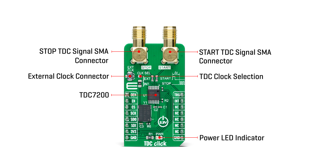
The TDC Click Board™ as its foundation uses the TDC7200, a time-to-digital converter for time-of-flight (ToF) applications for LIDAR and ultrasonic from Texas Instruments. This stopwatch IC is used to measure the time between a single event known as time-of-flight (an edge on START signal) and multiple subsequent events (an edge on STOP signal), which are brought to the onboard SMA connectors marked as START and STOP. The user also can pair this Click board™ with some external board that contains the TDC1000 (ultrasonic analog front-end) and become a part of a complete ultrasonic sensing solution for measurements such as water, gas, and heat flow meter.
The TDC7200 has an internal self-calibrated time base which compensates for drift over time and temperature used to measure time with accuracy in the order of picoseconds. When placed in the Autonomous Multi-Cycle Averaging mode of operation, the TDC7200 can be optimized for low system power consumption. The host can go to sleep to save power, and the TDC can wake it up upon completion of the measurement sequence.
The TDC7200 also needs an external reference clock used to calibrate the internal time-base accurately. All digital circuits inside the device also use this reference clock; thus, the clock has to be available and stable at all times when the device is enabled. For this reason, there is the possibility of selecting an external clock connected to a miniature coaxial N.FL series connector or an internal one by an onboard 8MHz crystal that can be activated via an OEN pin routed on the AN pin of the mikroBUS™ socket. Selection can be performed by onboard SMD jumper labeled as CLK SEL to an appropriate position marked as EXT and INT.
The TDC7200 communicates with MCU using the standard SPI serial interface with a maximum frequency of 20MHz. In addition, it also uses several additional GPIO pins such as the EN pin routed on the RST pin of the mikroBUS™ socket used as a reset to all digital circuits in the TDC7200, TRG pin routed on the PWM pin of the mikroBUS™ socket as a start measurement trigger and INT pin which determine TDC measurement completion.
The TDC Click Board™ can be operated only with a 3.3V logic voltage level. The board must perform appropriate logic voltage level conversion before use with MCUs with different logic levels. However, the Click board™ comes equipped with a library containing functions and an example code that can be used, as a reference, for further development.
Specifications
| Type | Clock generator |
| Applications | Can be used for time-of-flight and flow meter applications where zero and low flow measurements require high accuracy |
| On-board modules | TDC7200 - time-to-digital converter for time-of-flight (ToF) applications for LIDAR and ultrasonic from Texas Instruments |
| Key Features | Low power consumption, Autonomous Multi-Cycle Averaging mode, SPI interface for configuration and register access, supports up to 5 STOP signals, internal self-calibrated time base which compensates for drift over time and temperature, and more |
| Interface | SPI |
| Compatibility | mikroBUS |
| Click board size | M (42.9 x 25.4 mm) |
| Input Voltage | 3.3V |
Pinout diagram
This table shows how the pinout on TDC Click corresponds to the pinout on the mikroBUS™ socket (the latter shown in the two middle columns).
| Notes | Pin | Pin | Notes | ||||
|---|---|---|---|---|---|---|---|
| Onboard Crystal Enable | OEN | 1 | AN | PWM | 16 | TRG | Start Measurement Trigger |
| Enable | EN | 2 | RST | INT | 15 | INT | Interrupt |
| SPI Chip Select | CS | 3 | CS | RX | 14 | NC | |
| SPI Clock | SCK | 4 | SCK | TX | 13 | NC | |
| SPI Data OUT | SDO | 5 | MISO | SCL | 12 | NC | |
| SPI Data IN | SDI | 6 | MOSI | SDA | 11 | NC | |
| Power Supply | 3.3V | 7 | 3.3V | 5V | 10 | NC | |
| Ground | GND | 8 | GND | GND | 9 | GND | Ground |
Onboard settings and indicators
| Label | Name | Default | Description |
|---|---|---|---|
| LD1 | PWR | - | Power LED Indicator |
| JP1 | CLK SEL | Left | TDC Clock Selection EXT/INT: Upper position EXT, Lower position INT |
TDC Click electrical specifications
| Description | Min | Typ | Max | Unit |
|---|---|---|---|---|
| Supply Voltage | - | 3.3 | - | V |
| Resolution | - | 55 | - | ps |
| External Clock | - | 8 | - | MHz |
| Operating Temperature Range | -40 | +25 | +85 | °C |
Software Support
We provide a library for the TDC Click as well as a demo application (example), developed using MikroElektronika compilers. The demo can run on all the main MikroElektronika development boards.
Package can be downloaded/installed directly from NECTO Studio Package Manager(recommended way), downloaded from our LibStock™ or found on Mikroe github account.
Library Description
This library contains API for TDC Click driver.
Key Functions
tdc_cfg_setup- Config Object Initialization function.tdc_init- Initialization function.tdc_default_cfg- Click Default Configuration function.
Example Description
This library contains an API for the TDC Click driver. This demo application shows the use of a TDC Click board™.
The demo application is composed of two sections :
void application_task ( void )
{
    static uint32_t p_time[ 5 ];
    static uint32_t p_clock_count[ 5 ];
    static uint32_t p_tof[ 5 ];

    tdc_start_measurement( &tdc );

    while ( tdc_get_trg( &tdc ) == 0 );

    tdc_gen_pulse( &tdc_pulse, pulse_us, num_stops );

    while ( tdc_get_interrupt( &tdc ) == 1 );

    tdc_get_measurement( &tdc, TDC_MCU_CLOCK_MODE_168_MHZ, count_stop, p_time, p_clock_count, p_tof );

    log_printf( &logger, " Time[ 0 ]        = %lurn", p_time[ 0 ] );
    log_printf( &logger, " Time[ 1 ]        = %lurn", p_time[ 1 ] );
    log_printf( &logger, " Time[ 2 ]        = %lurn", p_time[ 2 ] );
    log_printf( &logger, "- - - - - - - - - - - - - -rn" );

    log_printf( &logger, " Clock count[ 0 ] = %lurn", p_clock_count[ 0 ] );
    log_printf( &logger, " Clock count[ 1 ] = %lurn", p_clock_count[ 1 ] );
    log_printf( &logger, " Clock count[ 2 ] = %lurn", p_clock_count[ 2 ] );
    log_printf( &logger, "- - - - - - - - - - - - - -rn" );

    log_printf( &logger, " TOF[ 0 ]         = %u usrn", p_tof[ 0 ] );
    log_printf( &logger, " TOF[ 1 ]         = %u usrn", p_tof[ 1 ] );
    log_printf( &logger, " TOF[ 2 ]         = %u usrn", p_tof[ 2 ] );
    log_printf( &logger, "---------------------------rn" );
    Delay_ms( 1000 );
}
The full application code, and ready to use projects can be installed directly from NECTO Studio Package Manager(recommended way), downloaded from our LibStock™ or found on Mikroe github account.
Other Mikroe Libraries used in the example:
- MikroSDK.Board
- MikroSDK.Log
- Click.Tdc
Additional Notes and Information
Depending on the development board you are using, you may need USB UART click, USB UART 2 click or RS232 click to connect to your PC, for development systems with no UART to USB interface available on the board. The terminal available in all MikroElektronika compilers, or any other terminal application of your choice, can be used to read the message.
mikroSDK
This Click board™ is supported with mikroSDK - MikroElektronika Software Development Kit. To ensure proper operation of mikroSDK compliant Click board™ demo applications, mikroSDK should be downloaded from the LibStock and installed for the compiler you are using.
Tableau à clic TDC
Frequently Asked Questions
Have a Question?
Be the first to ask a question about this.