


Mikroelektronika d.o.o.
Carte à clic ISO ADC 5
Carte à clic ISO ADC 5
SKU: MIKROE-4758
Impossible de charger la disponibilité du service de retrait
Overview
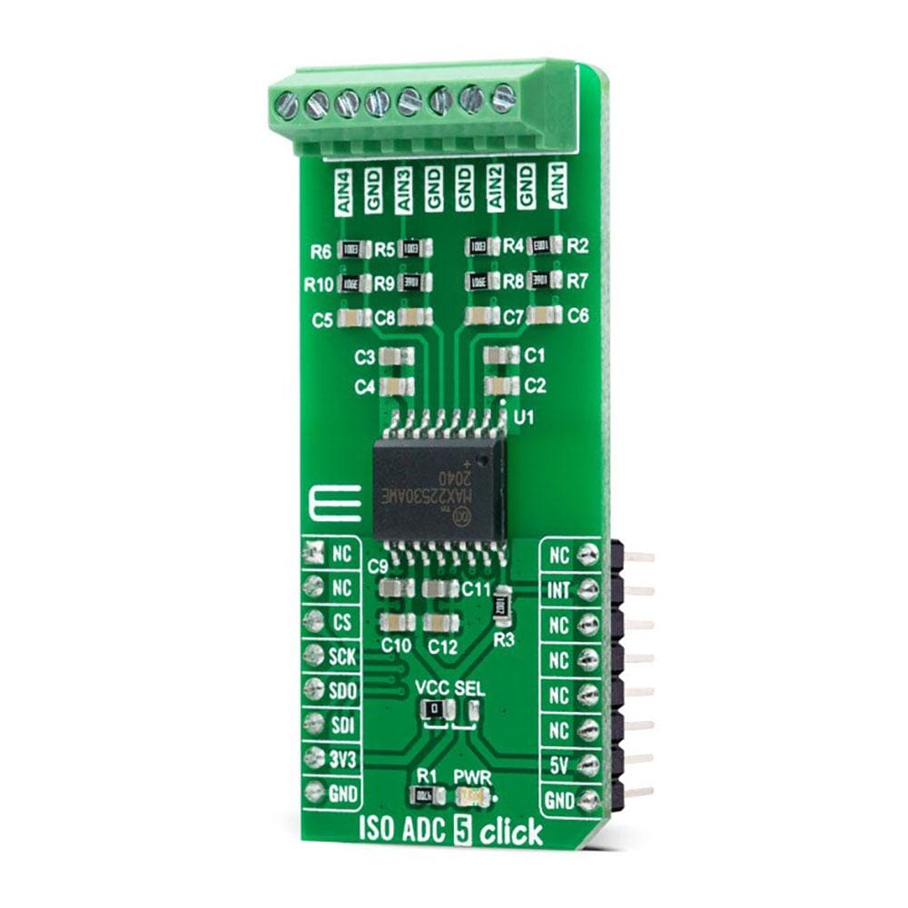
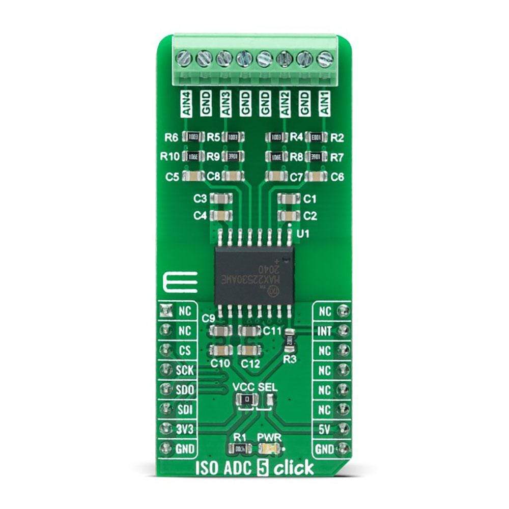
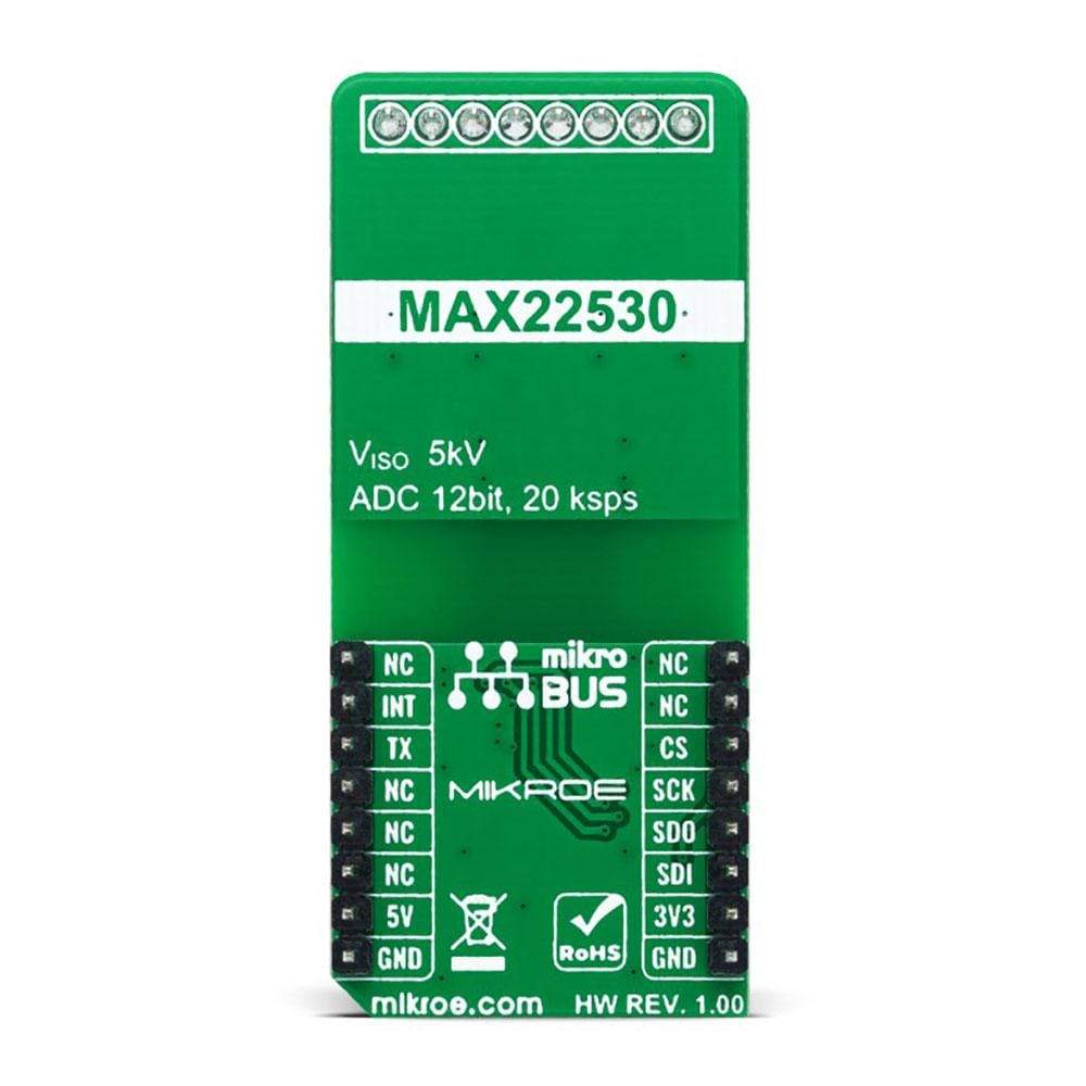
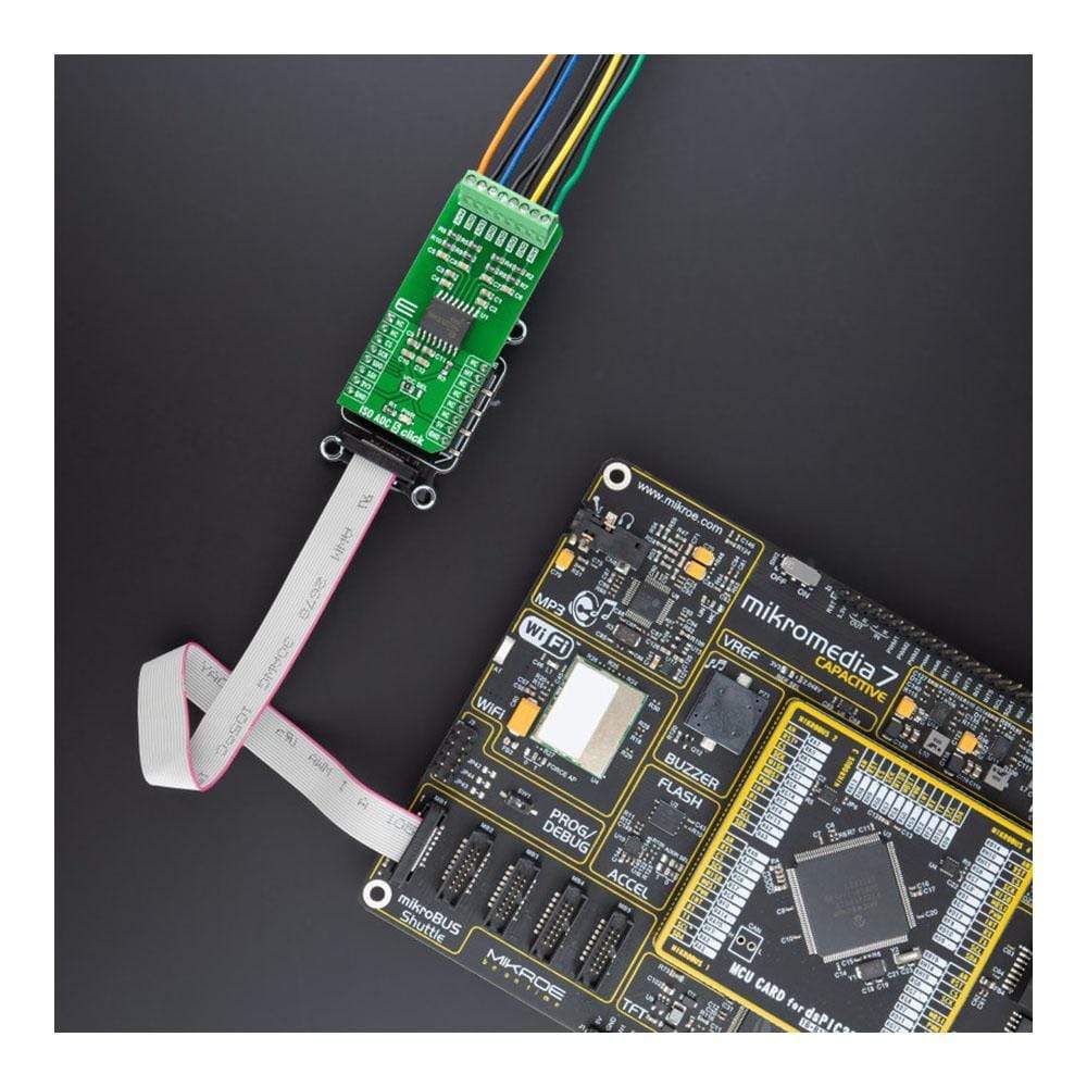
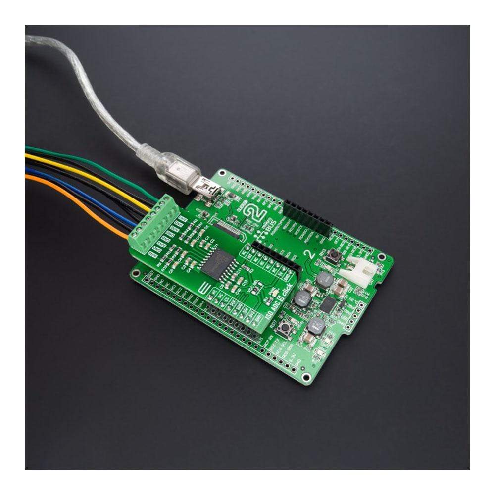
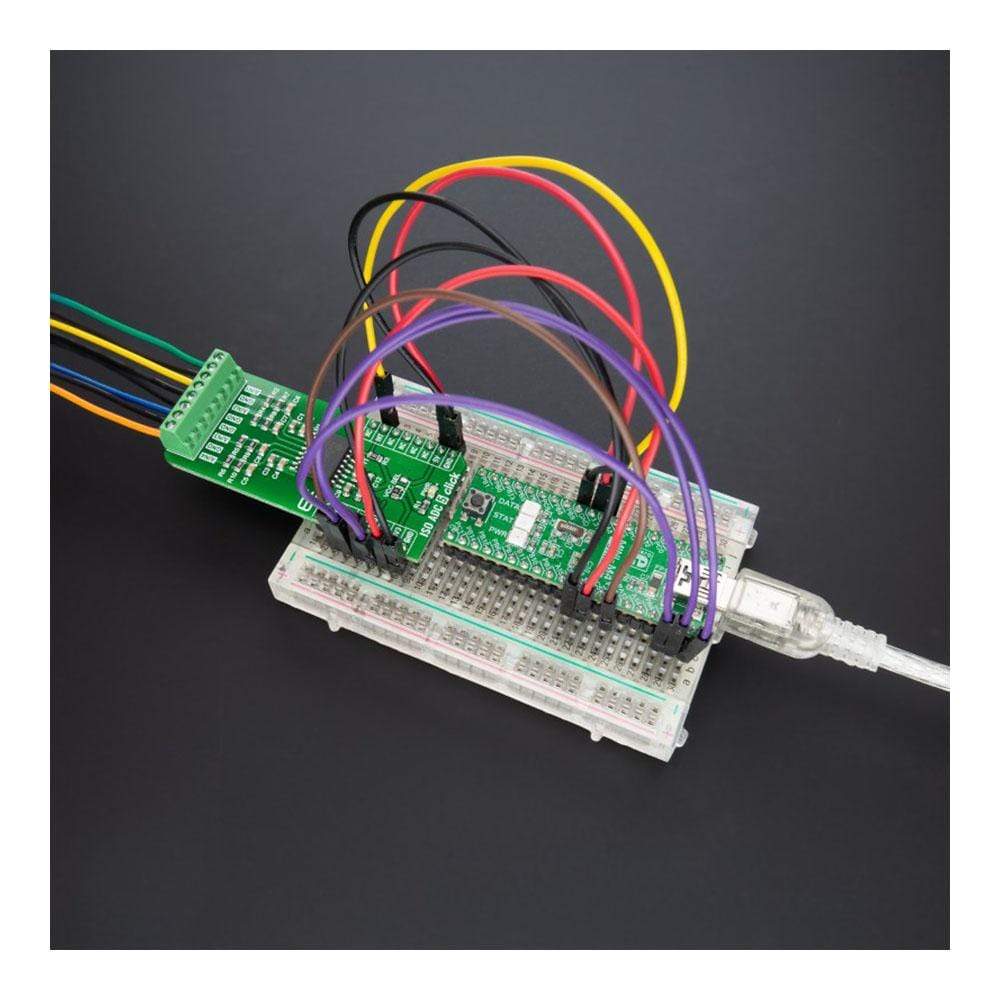
The ISO ADC 5 Click Board™ is a compact add-on board that contains quad-channel isolated ADC with field supply. This board features the MAX22530, galvanically isolated, 4-channel, multiplexed, 12-bit, analogue-to-digital converter (ADC), providing 5kVRMS isolation from Maxim Integrated. The ADC and all field-side circuits are powered by an integrated, isolated DC-DC converter that can verify field-side functionality even when there is no input signal or other field-side supply. The 12-bit ADC core has a sample rate of typically 20ksps per channel, where ADC data is available through the SPI interface. This Click Board™ is ideal for high-density, multi-range, group-isolated, binary-input modules and provides a complete solution to any system requiring monitoring inputs without a separate isolated power supply.
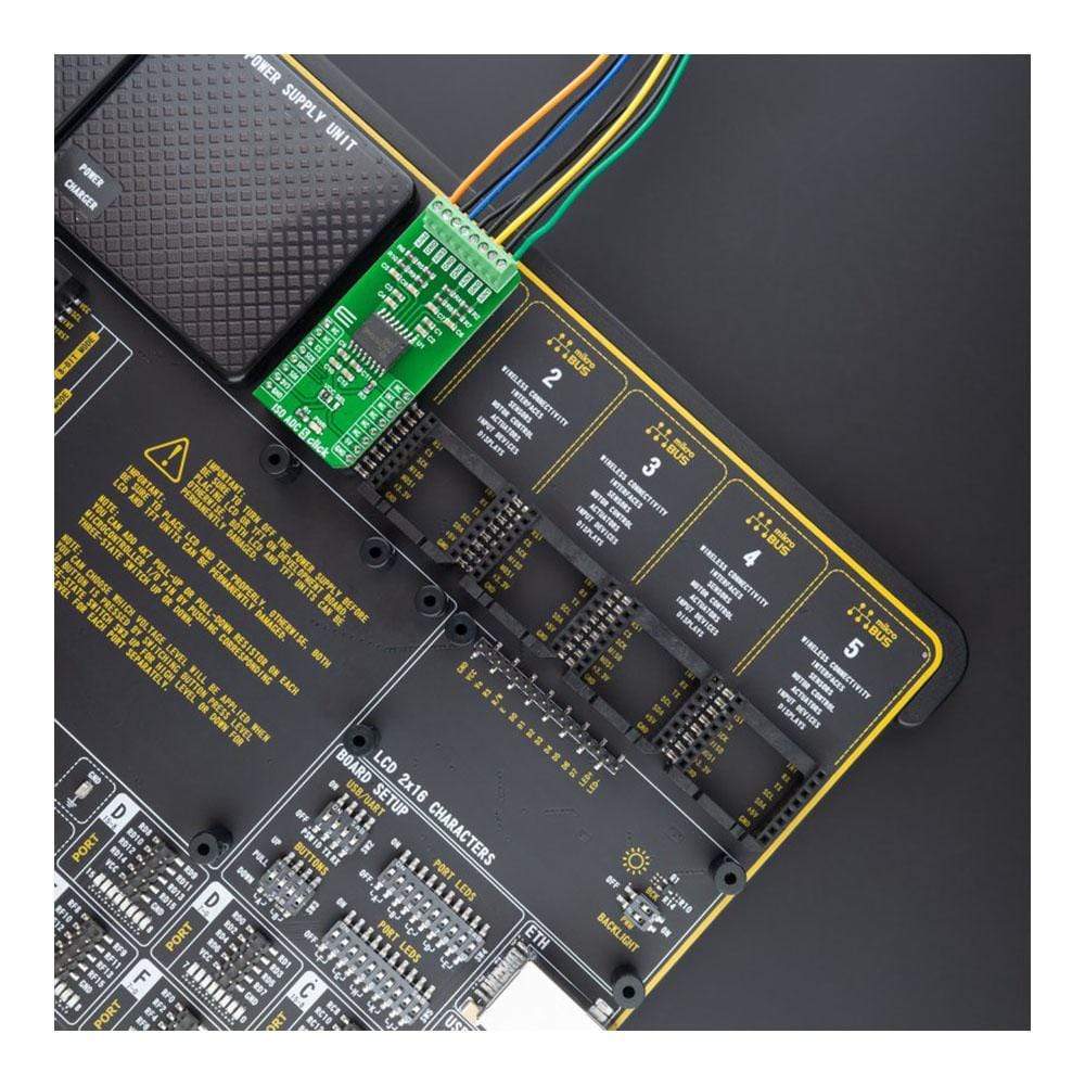
The ISO ADC 5 Click Board™ is supported by a mikroSDK compliant library, which includes functions that simplify software development. This Click Board™ comes as a fully tested product, ready to be used on a system equipped with the mikroBUS™ socket.
Downloads
Le ISO ADC 5 Click Board™ est une carte complémentaire compacte qui contient un ADC isolé à quatre canaux avec alimentation de terrain. Cette carte est équipée du convertisseur analogique-numérique (ADC) MAX22530, galvaniquement isolé, multiplexé, à 4 canaux, 12 bits, offrant une isolation de 5 kVRMS de Maxim Integrated. L'ADC et tous les circuits côté terrain sont alimentés par un convertisseur CC-CC isolé intégré qui peut vérifier la fonctionnalité côté terrain même lorsqu'il n'y a pas de signal d'entrée ou d'autre alimentation côté terrain. Le cœur ADC 12 bits a une fréquence d'échantillonnage de 20 kps par canal, où les données ADC sont disponibles via l'interface SPI. Cette Click Board™ est idéale pour les modules d'entrée binaire à haute densité, multi-plage, isolés par groupe et offre une solution complète à tout système nécessitant des entrées de surveillance sans alimentation isolée séparée.
Le Carte à clic ISO ADC 5™ est pris en charge par une bibliothèque compatible mikroSDK, qui comprend des fonctions qui simplifient le développement logiciel. Cette Click Board™ est un produit entièrement testé, prêt à être utilisé sur un système équipé du socket mikroBUS™.
| General Information | |
|---|---|
Part Number (SKU) |
MIKROE-4758
|
Manufacturer |
|
| Physical and Mechanical | |
Weight |
0.02 kg
|
| Other | |
EAN |
8606027383465
|
Frequently Asked Questions
Have a Question?
Be the first to ask a question about this.