


Mikroelektronika d.o.o.
Carte à clic DAC 10
Carte à clic DAC 10
SKU: MIKROE-4732
Impossible de charger la disponibilité du service de retrait


Key Features
Overview
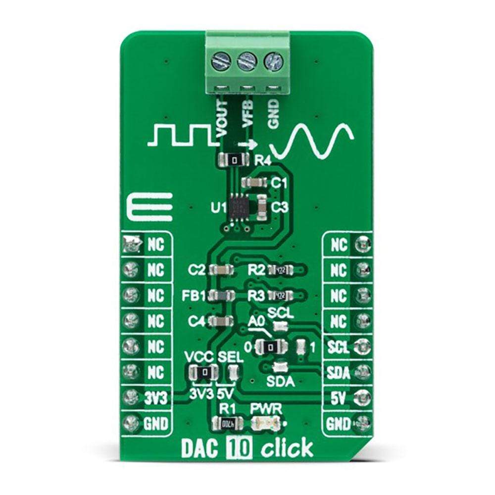
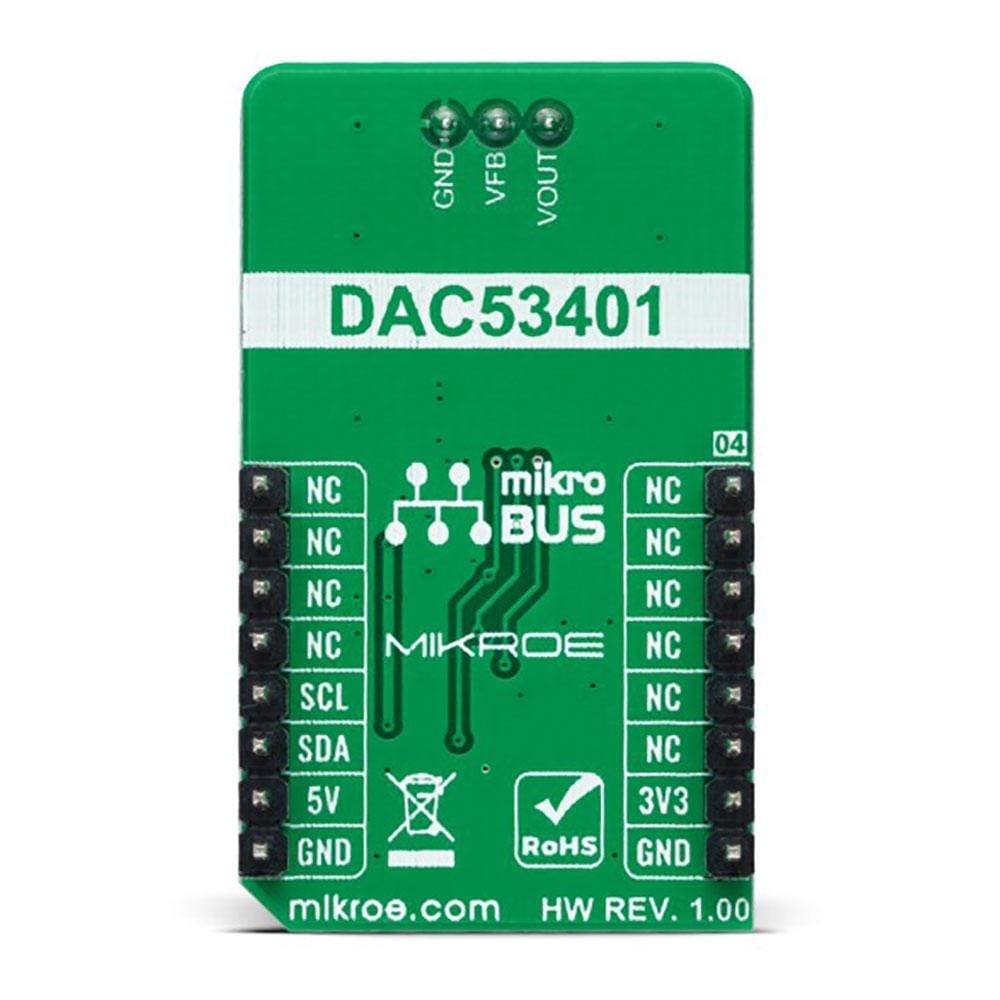
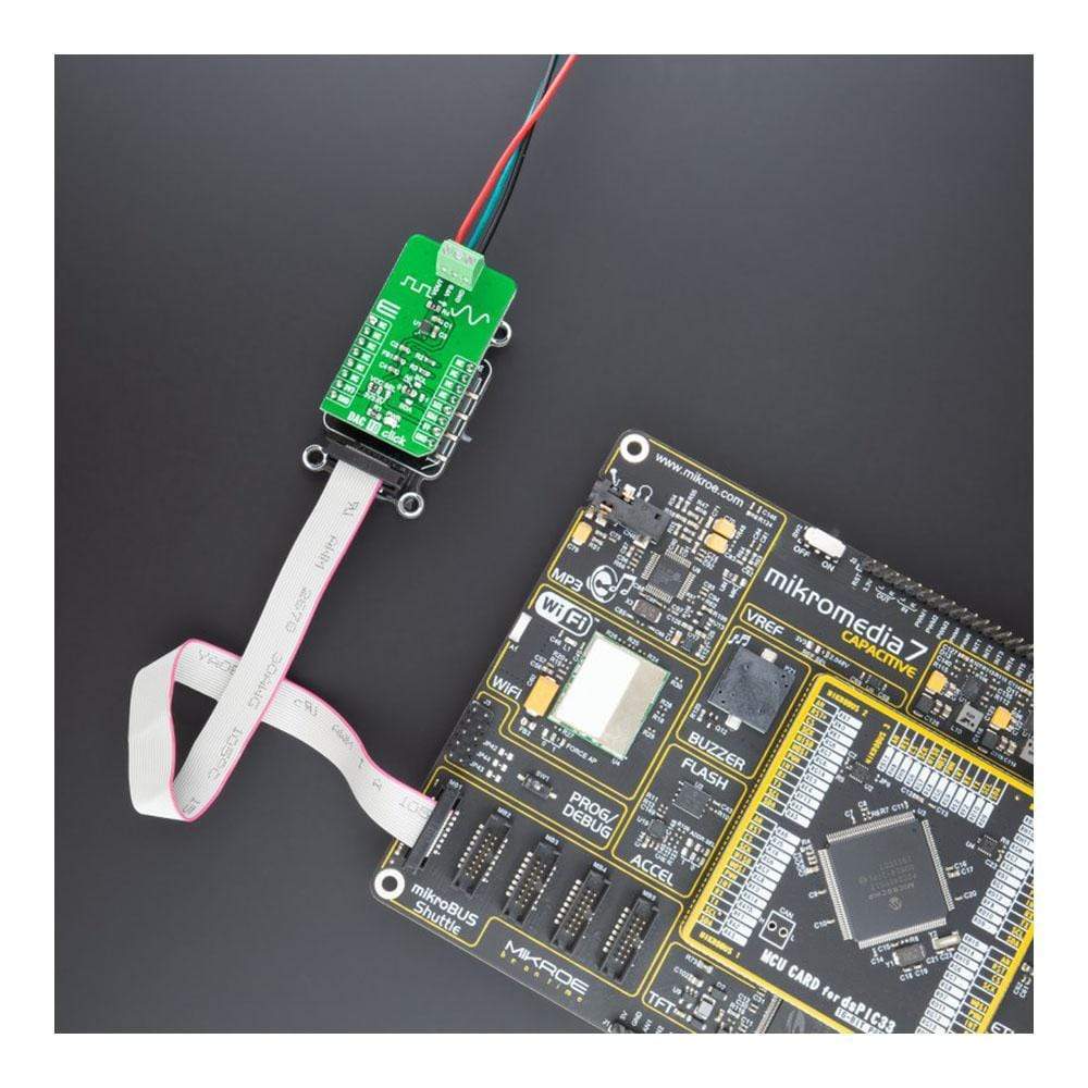
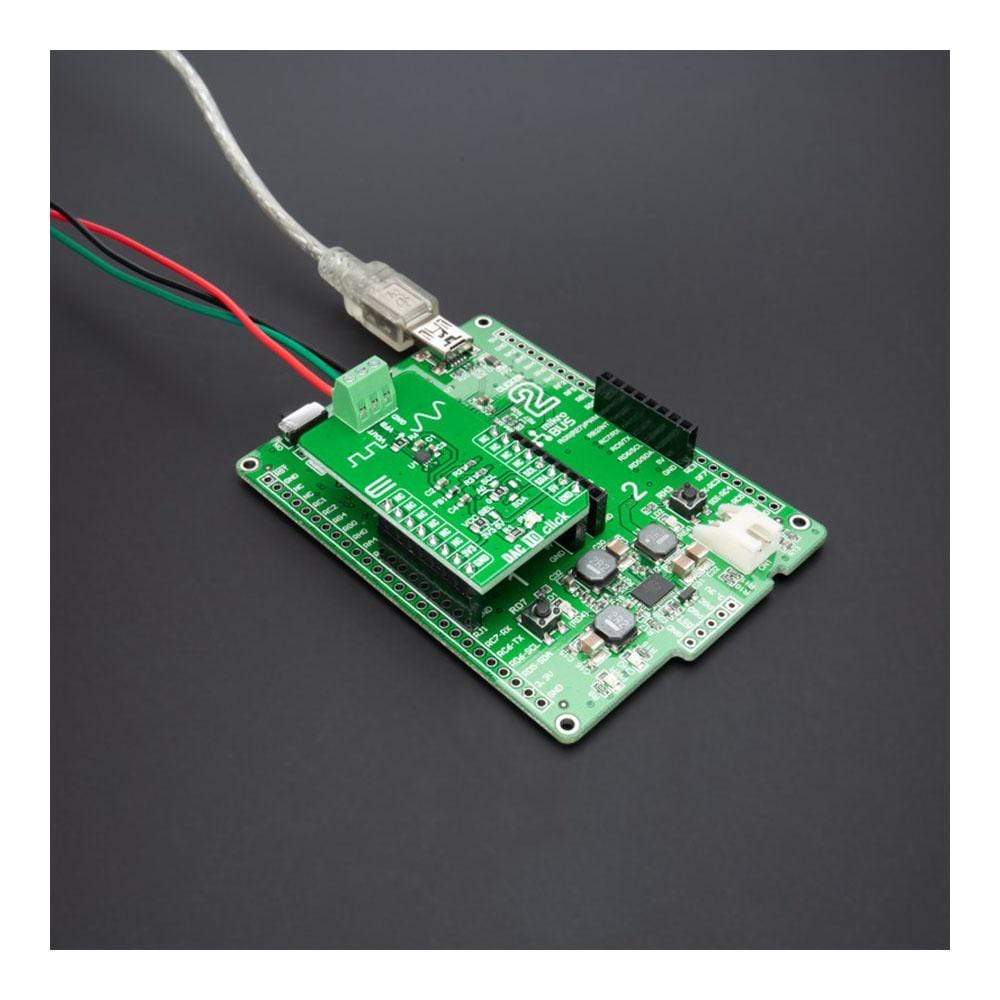
The DAC 10 Click Board™ is a compact add-on board that contains a fully-featured, highly accurate digital-to-analogue converter. This board features the DAC53401, a 10-bit voltage-output smart digital-to-analogue converter from Texas Instruments. This device consumes extremely low power and has a nonvolatile memory (NVM), an internal reference, and an I2C serial interface with a configurable slave address. It operates with either an internal reference or the power supply as a reference and provides full-scale output from 1.8V to 5.5V.
The DAC10 Click Board™ is a compact add-on board that contains a high-performance data converter that represents an excellent choice for applications such as LED and general-purpose bias point generation, power supply control, programmable reference, and more.
Downloads
Le DAC 10 Click Board™ est une carte complémentaire compacte qui contient un convertisseur numérique-analogique complet et extrêmement précis. Cette carte comprend le DAC53401, un convertisseur numérique-analogique intelligent à sortie de tension 10 bits de Texas Instruments. Cet appareil consomme extrêmement peu d'énergie et dispose d'une mémoire non volatile (NVM), d'une référence interne et d'une interface série I2C avec une adresse esclave configurable. Il fonctionne soit avec une référence interne, soit avec l'alimentation comme référence et fournit une sortie pleine échelle de 1,8 V à 5,5 V.
Le Carte à clic DAC10™ est une carte complémentaire compacte qui contient un convertisseur de données hautes performances qui représente un excellent choix pour des applications telles que la génération de points de polarisation LED et à usage général, le contrôle de l'alimentation, la référence programmable, etc.
| General Information | |
|---|---|
Part Number (SKU) |
MIKROE-4732
|
Manufacturer |
|
| Physical and Mechanical | |
Weight |
0.02 kg
|
| Other | |
EAN |
8606027383267
|
Frequently Asked Questions
Have a Question?
Be the first to ask a question about this.