


Mikroelektronika d.o.o.
Carte à clic sans balais 14
Carte à clic sans balais 14
SKU: MIKROE-4648
Impossible de charger la disponibilité du service de retrait


Overview
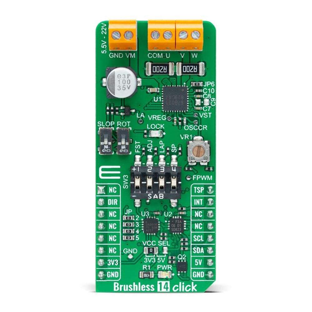
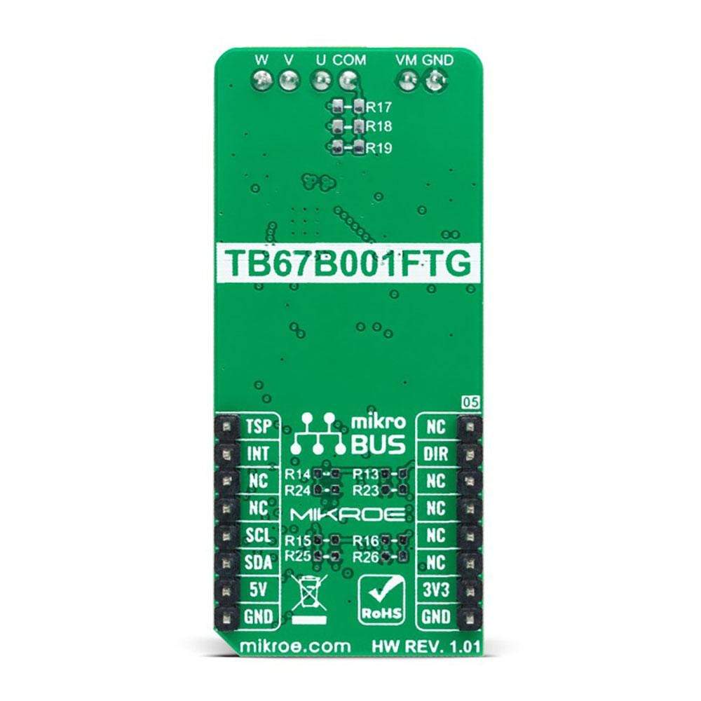
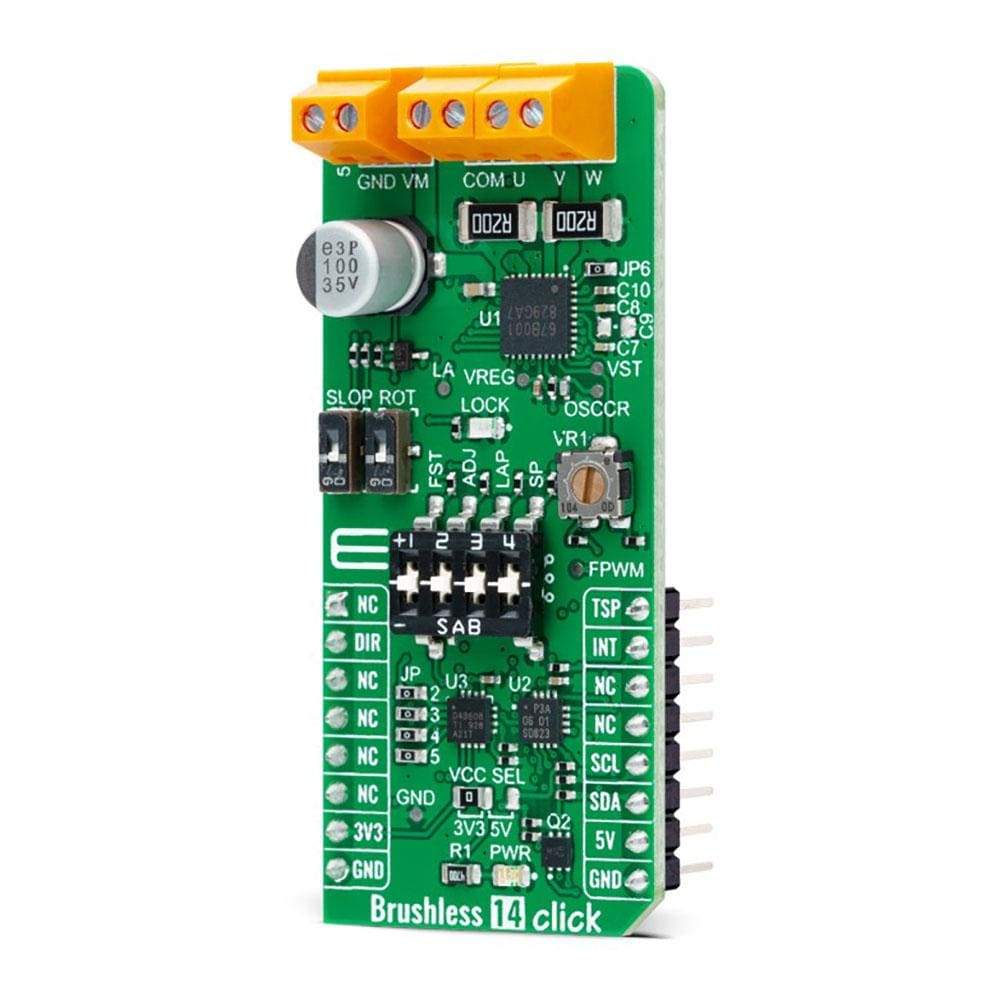
The Brushless 14 Click Board™ is a compact add-on board suitable for controlling BLDC motors with any MCU. This board features the TB67B001FTG, a three-phase, brushless, Hall sensorless driver IC from Toshiba Semiconductor. It comes with a 150-degree wide-angle commutation drive, contributing to lower vibration and motor noise, while a rotation speed up to 30,000rpm (rotations per minute when a 4-pole motor is used) can be achieved through a high-speed PWM and improved cooling.
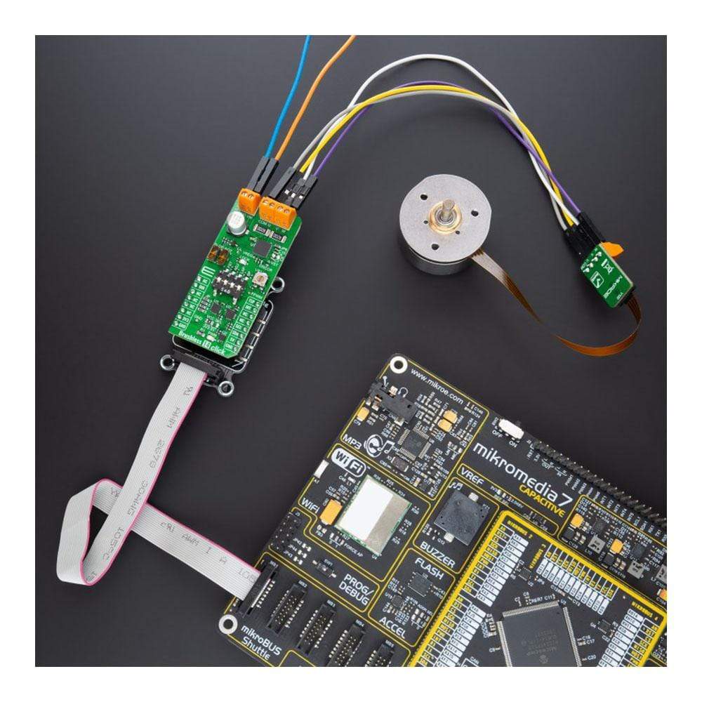
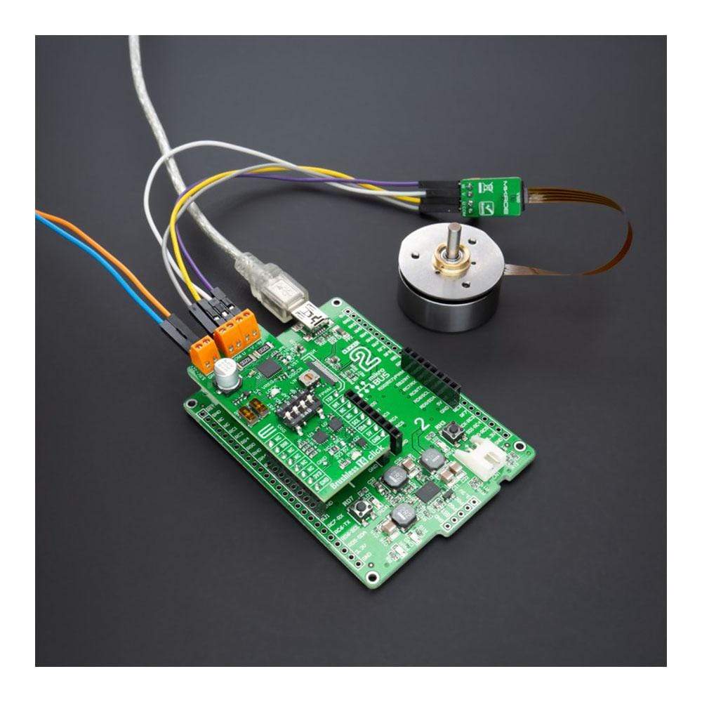
This Brushless 14 Click Board™ makes the perfect solution for delivering quiet, cool operation to home appliances and office automation equipment.
Downloads
Le Planche à 14 clics sans balais™ est une carte complémentaire compacte adaptée au contrôle des moteurs BLDC avec n'importe quel microcontrôleur. Cette carte est équipée du TB67B001FTG, un circuit intégré de commande triphasé, sans balais et sans capteur à effet Hall de Toshiba Semiconductor. Il est équipé d'un variateur de commutation grand angle de 150 degrés, contribuant à réduire les vibrations et le bruit du moteur, tandis qu'une vitesse de rotation allant jusqu'à 30 000 tr/min (rotations par minute lorsqu'un moteur à 4 pôles est utilisé) peut être obtenue grâce à un PWM à grande vitesse et à un refroidissement amélioré.
Cette carte Brushless 14 Click Board™ constitue la solution idéale pour assurer un fonctionnement silencieux et frais des appareils électroménagers et des équipements de bureautique.
| General Information | |
|---|---|
Part Number (SKU) |
MIKROE-4648
|
Manufacturer |
|
| Physical and Mechanical | |
Weight |
0.02 kg
|
| Other | |
EAN |
8606027383328
|
Frequently Asked Questions
Have a Question?
Be the first to ask a question about this.