Planche à clic Stepper 15
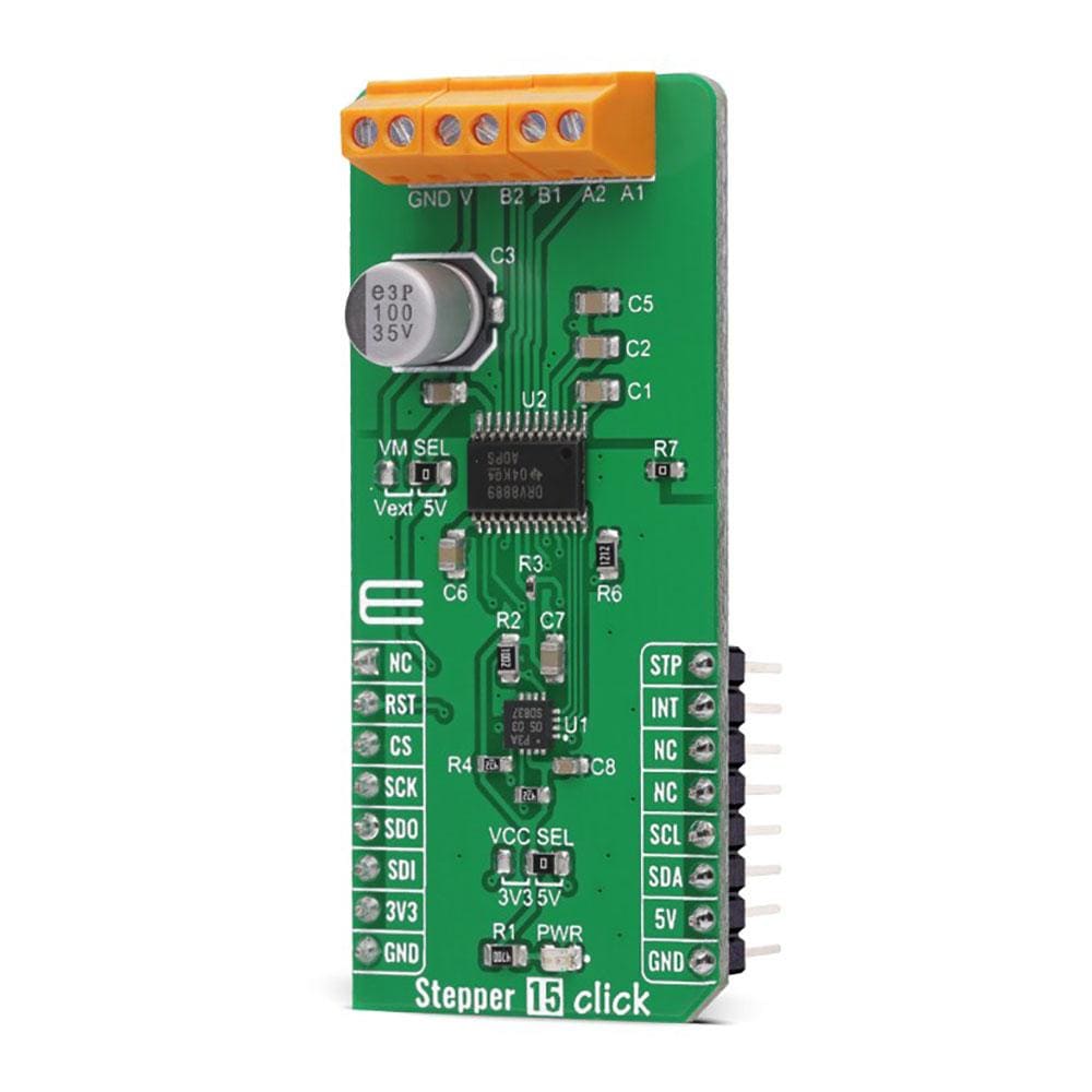
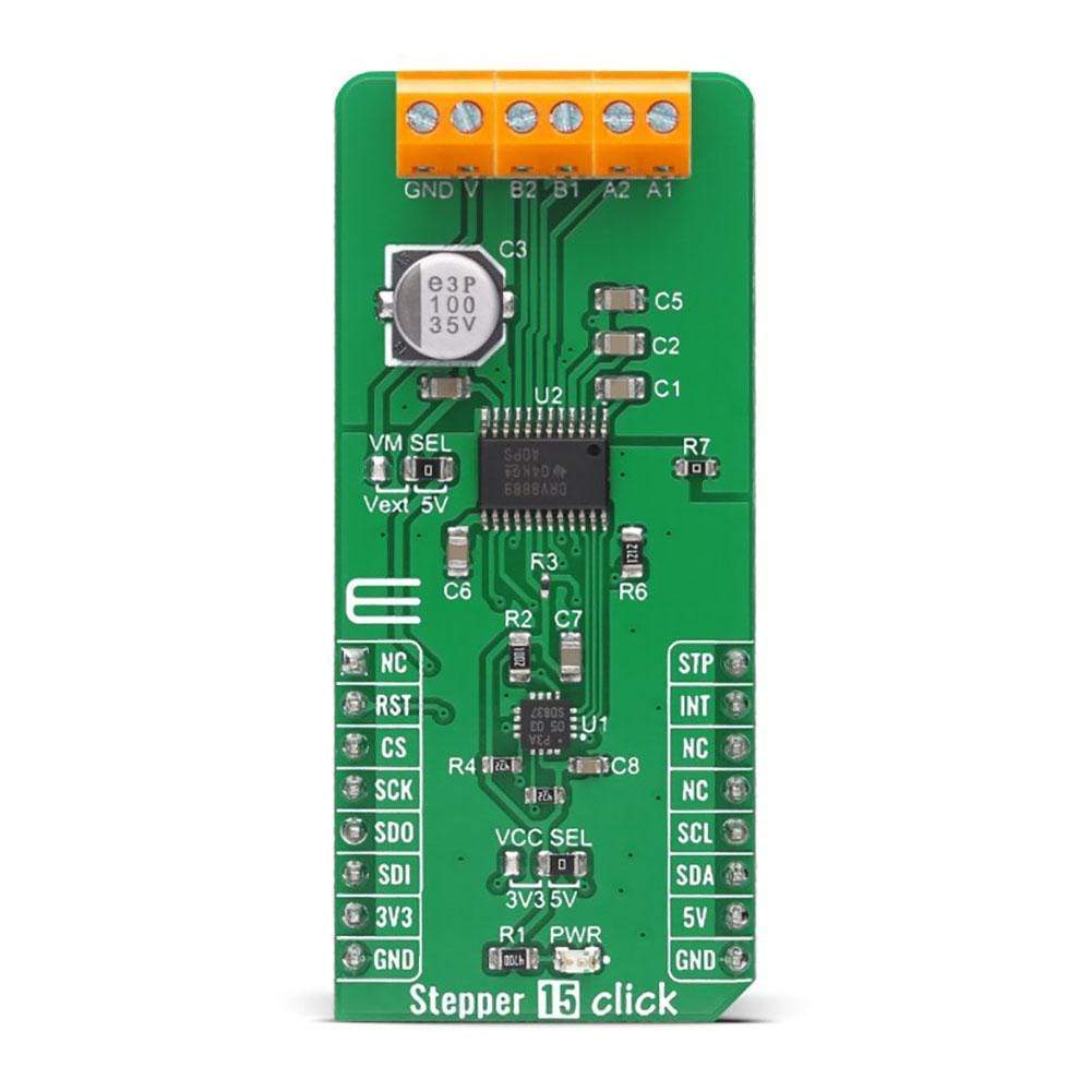
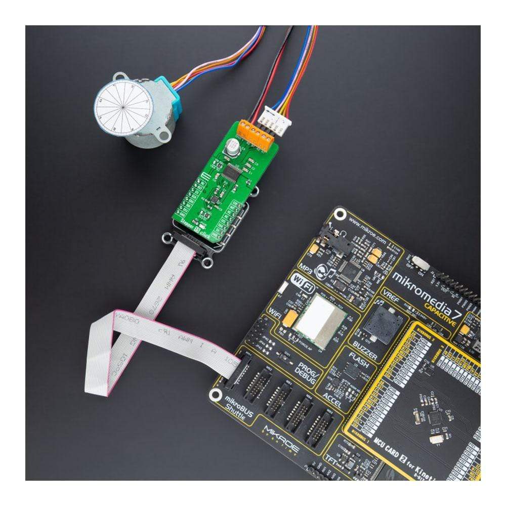
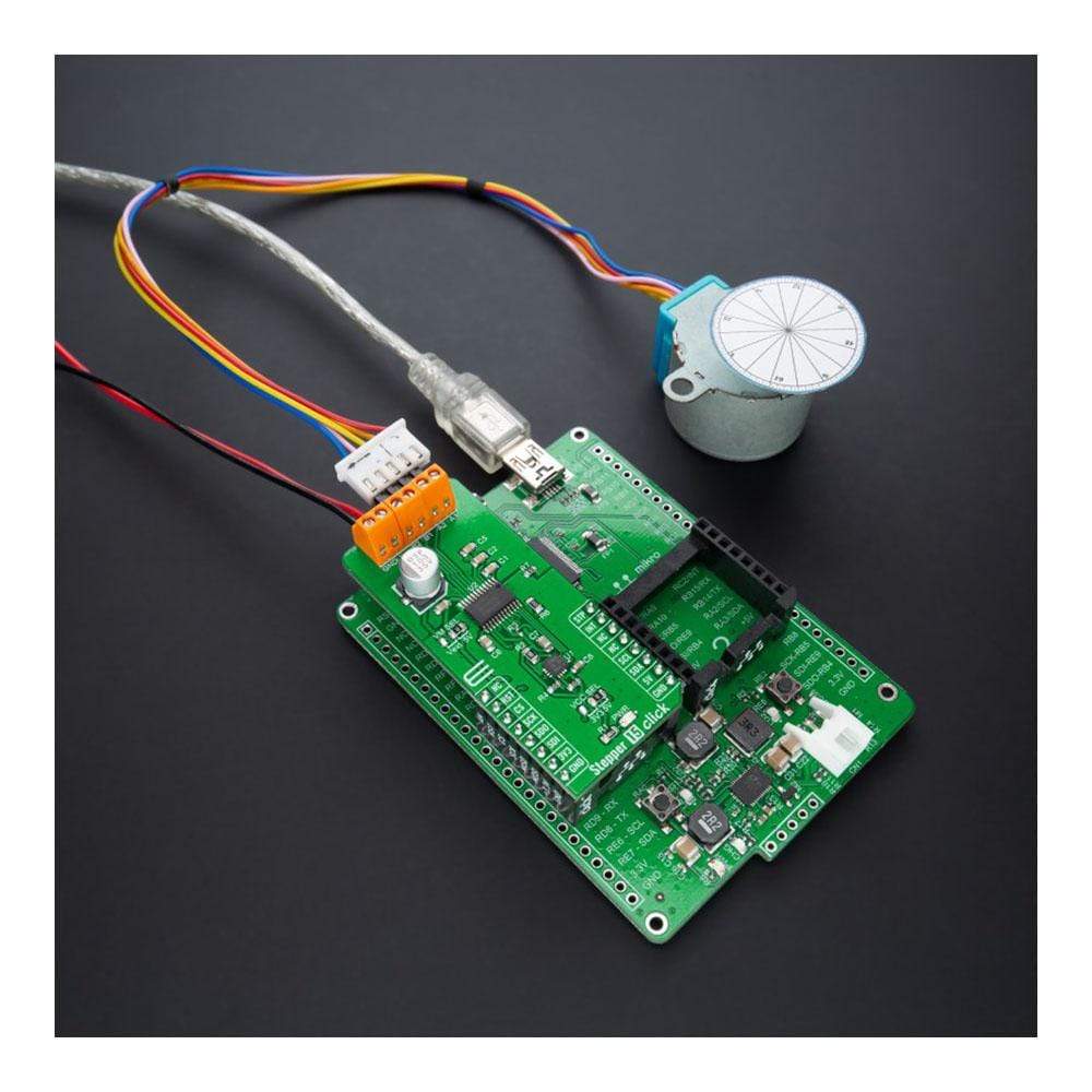
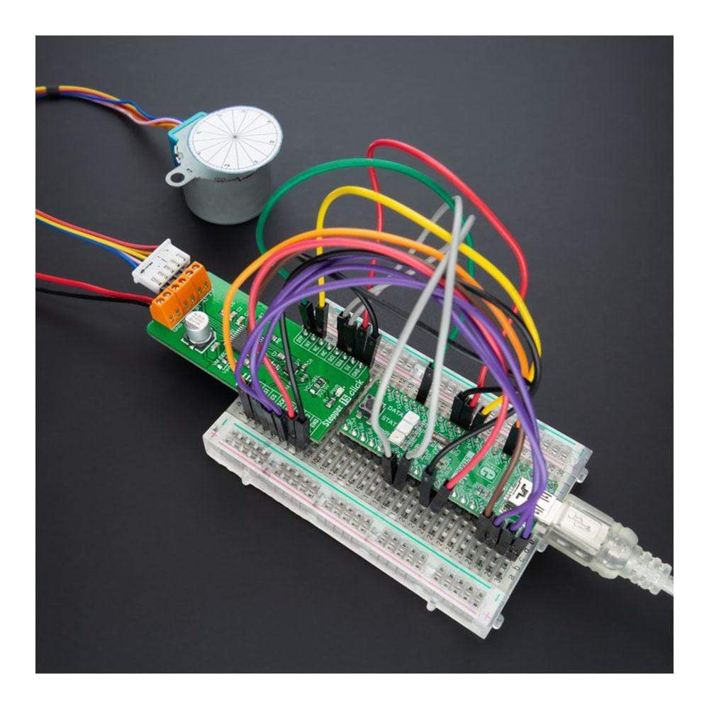
Le Stepper 15 Click Board™ est une carte complémentaire compacte qui contient un pilote de moteur pas à pas bipolaire. Cette carte comprend le DRV8889A, un pilote de moteur pas à pas automobile avec détection de courant et de calage intégrée de Texas Instruments. Il prend en charge jusqu'à 1,5 A de courant pleine échelle avec un indexeur de micropas interne, une technologie de décroissance de réglage intelligent, un algorithme avancé de détection de calage et une détection de courant intégrée, éliminant ainsi le besoin de résistances de détection de puissance. Avec une interface STEP/DIR simple, l'appareil prend en charge jusqu'à 1/256 niveaux de micropas pour permettre un profil de mouvement fluide. De plus, un algorithme avancé de détection de calage permet aux utilisateurs de détecter si le moteur s'est arrêté et de prendre les mesures nécessaires, améliorant ainsi l'efficacité et réduisant le bruit. Ce Click Board™ convient à la commande de moteurs dans toute application qui exige un pilote de moteur pas à pas précis et sûr.
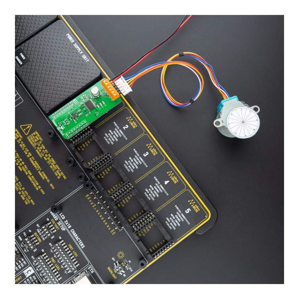
Le Stepper 15 Click Board™ est pris en charge par une bibliothèque compatible mikroSDK, qui comprend des fonctions qui simplifient le développement logiciel. Cette Click Board™ est un produit entièrement testé, prêt à être utilisé sur un système équipé du socket mikroBUS™.
How Does The Stepper 15 Click Board™ Work?
The Stepper 15 Click Board™ uses the DRV8889A, an integrated motor-driver solution for bipolar stepper motors from Texas Instruments. The DRV8889A integrates two N-channel power MOSFET H-bridges (disabled by default after Power-Up), integrated current sense and regulation circuitry, and a microstepping indexer. It can be powered with a supply voltage from 4.5 to 45V, providing an output current up to 2.4A peak, 1.5A full-scale, or 1.1A RMS.
The DRV8889A uses an integrated current-sense architecture which eliminates the need for two external power sense resistors. This architecture removes the power dissipated in the sense resistors using a current mirror approach and using the internal power MOSFETs for current sensing. It also includes an integrated torque DAC that allows the controller to scale the output current through a full-duplex, 4-wire synchronous SPI interface without needing to scale the voltage reference. The torque DAC allows the controller to save system power by decreasing the motor current consumption when high output torque is not required.
A simple STEP/DIR interface allows an external MCU to manage the direction and step rate of the stepper motor. The internal indexer can execute high-accuracy microstepping without requiring the MCU to handle the winding current level. The indexer can take the whole step, half step, and 1/4, 1/8, 1/16, 1/32, 1/64, 1/128, and 1/256 microstepping. Also, a noncircular half stepping mode is available for increased torque output at higher motor RPM in addition to a standard half stepping mode.
Unlike the STEP pin controlled by the PWM pin from the mikroBUS™ socket, other pins from the DRV8889A such as Sleep mode selection, fault indicator, direction selection, and device disable pin are controlled through a well-known 8bit I/O expander, the PCA9538 from NXP Semiconductor using the standard I2C 2-Wire interface with a maximum frequency of 400kHz. The PCA9538 also uses RST and INT pins from the mikroBUS™ socket as a hardware reset and interrupt function.
The Stepper 15 Click Board™ can operate with both 3.3V and 5V logic voltage levels selected via the VCC SEL jumper. It allows for both 3.3V and 5V capable MCUs to use the communication lines properly. Additionally, there is a possibility for stepper motor driver power supply selection via jumper labelled as VM SEL to supply the DRV8889A from an external input terminal in the range from 4.5 to 45V or with a 5V from mikroBUS™ power rail.
SPECIFICATIONS
Type | Stepper |
Applications | Can be used for driving motors in any application that demands a precise and safe step motor driver. |
On-board modules | DRV8889A - integrated motor-driver solution for bipolar stepper motors from Texas Instruments |
Key Features | Qualified for automotive, up to 1/256 microstepping, integrated current sense, various protection features, and more. |
Interface | SPI,I2C |
Compatibility | mikroBUS |
Click board size | L (57.15 x 25.4 mm) |
Input Voltage | 3.3V or 5V,External |
PINOUT DIAGRAM
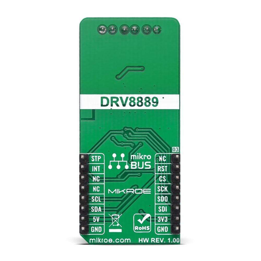
This table shows how the pinout of the Stepper 15 Click Board™ corresponds to the pinout on the mikroBUS™ socket (the latter shown in the two middle columns).
Notes | Pin | | Pin | Notes | |||
---|---|---|---|---|---|---|---|
NC | 1 | AN | PWM | 16 | STP | Step-Rate | |
Reset | RST | 2 | RST | INT | 15 | INT | Interrupt |
SPI Chip Select | CS | 3 | CS | RX | 14 | NC | |
SPI Clock | SCK | 4 | SCK | TX | 13 | NC | |
SPI Data OUT | SDO | 5 | MISO | SCL | 12 | SCL | I2C Clock |
SPI Data IN | SDI | 6 | MOSI | SDA | 11 | SDA | I2C Data |
Power Supply | 3.3V | 7 | 3.3V | 5V | 10 | 5V | Power Supply |
Ground | GND | 8 | GND | GND | 9 | GND | Ground |
ONBOARD SETTINGS AND INDICATORS
Label | Name | Default | Description |
---|---|---|---|
LD1 | PWR | - | Power LED Indicator |
JP1 | VM SEL | Right | DRV8889A Power Supply Selection Vext/5V: Left position Vext, Right position 5V |
JP2 | VCC SEL | Right | Logic Level Voltage Selection 3V3/5V: Left position 3V3, Right position 5V |
STEPPER 15 CLICK ELECTRICAL SPECIFICATIONS
Description | Min | Typ | Max | Unit |
---|---|---|---|---|
Supply Voltage VCC | 3.3 | - | 5 | V |
Supply Voltage Vext | 4.5 | - | 45 | V |
Maximum Output Current | - | - | 1.5 | A |
Step Resolution | 1/256 | - | 1 | μstep |
Operating Temperature Range | -40 | +25 | +125 | °C |
Software Support
We provide a library for the Stepper 15 Click Board™ as well as a demo application (example), developed using MikroElektronika compilers. The demo can run on all the main MikroElektronika development boards.
The package can be downloaded/installed directly from NECTO Studio The package Manager (recommended), downloaded from our LibStock™ or found on the mikroE Github account.
Library Description
This library contains API for Stepper 15 Click driver.
Key Functions
stepper15_make_one_step
- Stepper 15 make one step function.stepper15_set_direction
- Stepper 15 set direction function.stepper15_step_by_angle
- Stepper 15 step by angle function.
Example Description
void application_task ( void ) { log_printf( &logger, "---------------------------------rn" ); log_printf( &logger, " Clockwise motion rn" ); log_printf( &logger, " Angle of rotation : 90 degrees rn" ); log_printf( &logger, " Step speed : 85 %% rn" ); stepper15_set_direction ( &stepper15, STEPPER15_DIRECTION_CLOCKWISE ); stepper15_step_by_angle( &stepper15, step_speed - 15, 90, step_360 ); Delay_ms( 2000 ); log_printf( &logger, "---------------------------------rn" ); log_printf( &logger, " Counterclockwise motion rn" ); log_printf( &logger, " Angle of rotation : 180 degrees rn" ); log_printf( &logger, " Step speed : 85 %% rn" ); stepper15_set_direction ( &stepper15, STEPPER15_DIRECTION_COUNTERCLOCKWISE ); stepper15_step_by_angle( &stepper15, step_speed - 15, 180, step_360 ); Delay_ms( 2000 ); log_printf( &logger, "---------------------------------rn" ); log_printf( &logger, " Clockwise motion rn" ); log_printf( &logger, " Angle of rotation : 270 degrees rn" ); log_printf( &logger, " Step speed : 90 %% rn" ); stepper15_set_direction ( &stepper15, STEPPER15_DIRECTION_CLOCKWISE ); stepper15_step_by_angle( &stepper15, step_speed - 10, 270, step_360 ); Delay_ms( 2000 ); log_printf( &logger, "---------------------------------rn" ); log_printf( &logger, " Counterclockwise motion rn" ); log_printf( &logger, " Angle of rotation : 360 degrees rn" ); log_printf( &logger, " Step speed : 100 %% rn" ); stepper15_set_direction ( &stepper15, STEPPER15_DIRECTION_COUNTERCLOCKWISE ); stepper15_step_by_angle( &stepper15, step_speed, 360, step_360 ); Delay_ms( 2000 ); log_printf( &logger, "---------------------------------rn" ); log_printf( &logger, " Clockwise motion rn" ); log_printf( &logger, " Angle of rotation : 360 degrees rn" ); log_printf( &logger, " Step speed : 100 %% rn" ); stepper15_set_direction ( &stepper15, STEPPER15_DIRECTION_CLOCKWISE ); stepper15_step_by_angle( &stepper15, step_speed, 360, step_360 ); Delay_ms( 2000 ); } The complete application code, and ready-to-use projects can be installed directly from NECTO Studio The package Manager (recommended), downloaded from our LibStock™ or found on the mikroE Github account.
Other mikroE Libraries used in the example:
- MikroSDK.Board
- MikroSDK.Log
- Click.Stepper15
Additional Notes and Information
Depending on the development board you are using, you may needs a USB UART Click Board™, USB UART 2 Click Board™ or RS232 Click Board™ to connect to your PC, for development systems with no UART to USB interface available on the board. The terminal available in all MikroElektronika compilers, or any other terminal application of your choice, can be used to read the message.
MIKROSDK
The Stepper 15 Click Board™ is supported with mikroSDK - MikroElektronika Software Development Kit. To ensure proper operation of mikroSDK compliant Click board™ demo applications, mikroSDK should be downloaded from the LibStock and installed for the compiler you are using.
Planche à clic Stepper 15
Frequently Asked Questions
Have a Question?
Be the first to ask a question about this.