


Mikroelektronika d.o.o.
Tableau de clic ISM
Tableau de clic ISM
SKU: MIKROE-4625
Impossible de charger la disponibilité du service de retrait


Overview
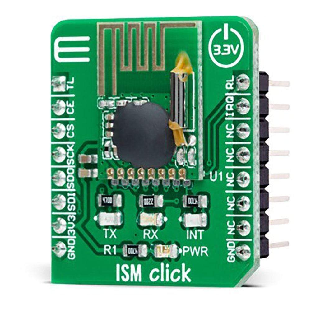
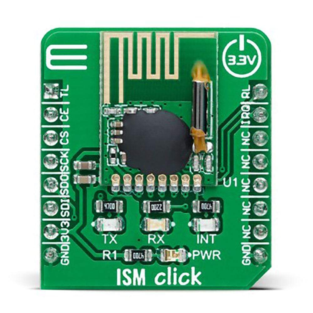
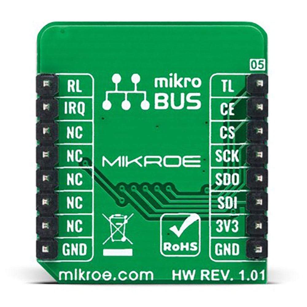
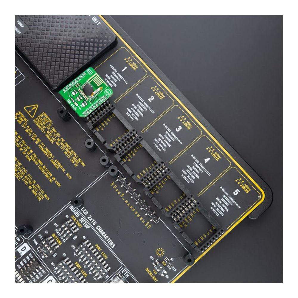
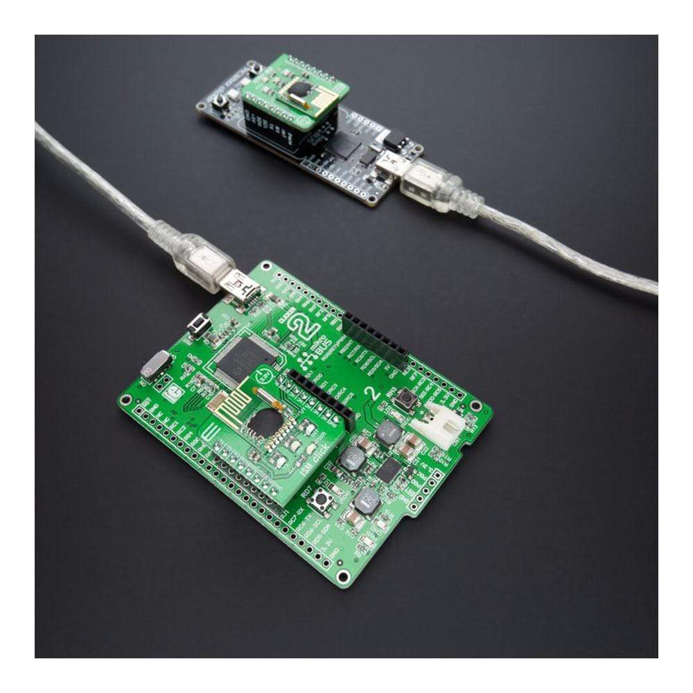
The ISM Click Board™ is a compact add-on board that contains a complete wireless RF digital data transceiver. This board features the RFM75, a low-power, high-performance 2.4GHz GFSK transceiver from RF Solutions. The RFM75 transceiver is configurable through SPI serial interface and operates with only 3.3V in the worldwide ISM frequency band from 2400MHz up to 2527MHz. The embedded packet processing engines enable their entire operation with a simple MCU as a radio system. Burst mode transmission and up to 2Mbps air data rate make it suitable for ultra-low power consumption applications.
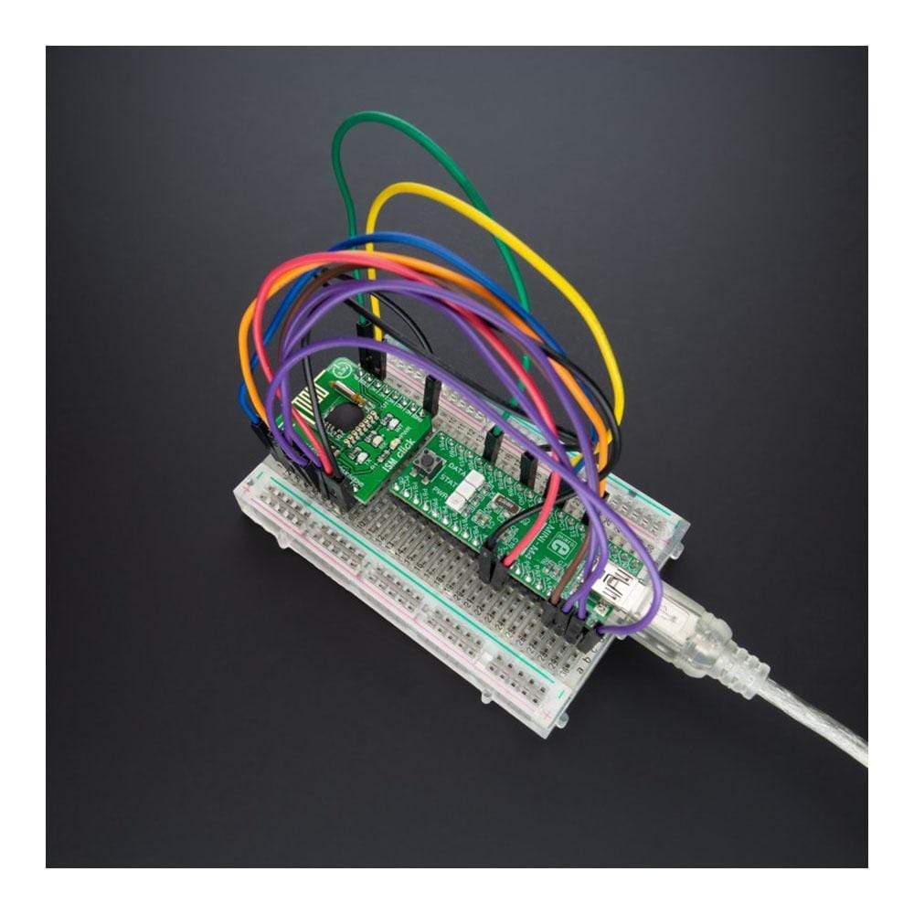
This ISM Click Board™ is ideal for home appliances, remote control applications, consumer electronics, and many more.
Downloads
Le Tableau à clic ISM™ est une carte complémentaire compacte qui contient un émetteur-récepteur de données numériques RF sans fil complet. Cette carte comprend le RFM75, un émetteur-récepteur GFSK 2,4 GHz à faible consommation et hautes performances de RF Solutions. L'émetteur-récepteur RFM75 est configurable via l'interface série SPI et fonctionne avec seulement 3,3 V dans la bande de fréquences ISM mondiale de 2400 MHz à 2527 MHz. Les moteurs de traitement de paquets intégrés permettent leur fonctionnement complet avec un simple MCU en tant que système radio. La transmission en mode rafale et le débit de données aérien jusqu'à 2 Mbps le rendent adapté aux applications à très faible consommation d'énergie.
Ce ISM Click Board™ est idéal pour les appareils électroménagers, les applications de télécommande, l'électronique grand public et bien d'autres.
| General Information | |
|---|---|
Part Number (SKU) |
MIKROE-4625
|
Manufacturer |
|
| Physical and Mechanical | |
Weight |
0.02 kg
|
| Other | |
EAN |
8606027382765
|
Frequently Asked Questions
Have a Question?
Be the first to ask a question about this.