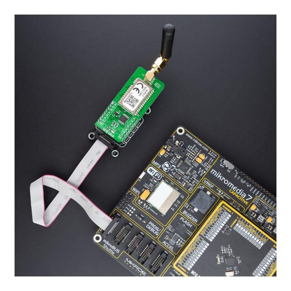
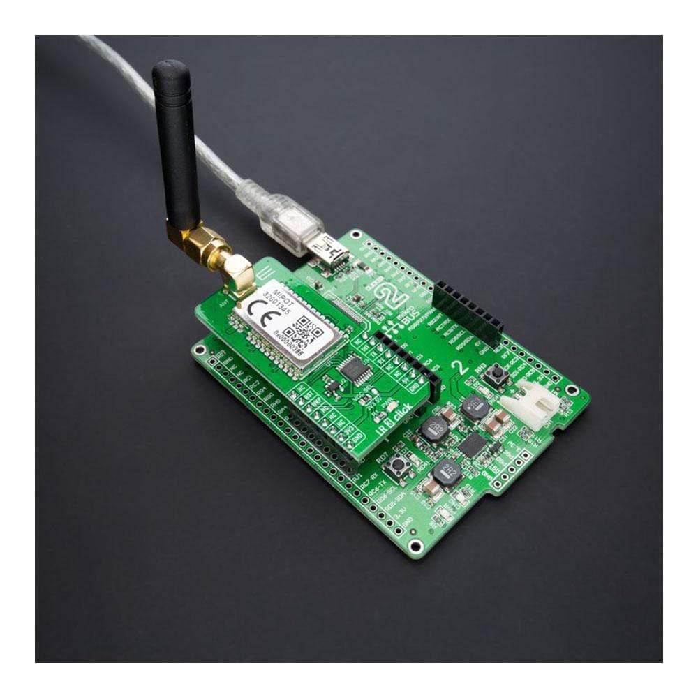
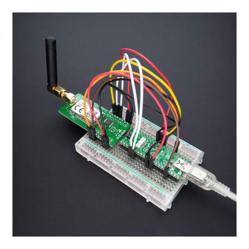
Tableau à clic LR 3
Tableau à clic LR 3
Key Features
- La carte Click Board™ est dotée d'un réseau sans fil robuste basé sur la technologie RF Lora®, d'une pile réseau complète, d'un cryptage des messages (AES128), d'une interface UART facile à utiliser et d'une faible consommation d'énergie.
- Basé sur le MIPOT 32001345, émetteur-récepteur longue portée basé sur la technologie RF Lora®
- Le LR 3 Click Board™ offre des solutions simples et fiables pour le développement de réseaux IoT à faible consommation et hautement intégrés, de systèmes de sécurité, de réseaux d'alarme et d'applications similaires qui nécessitent des solutions de mise en réseau simples et fiables
- mikroBUS : interface UART
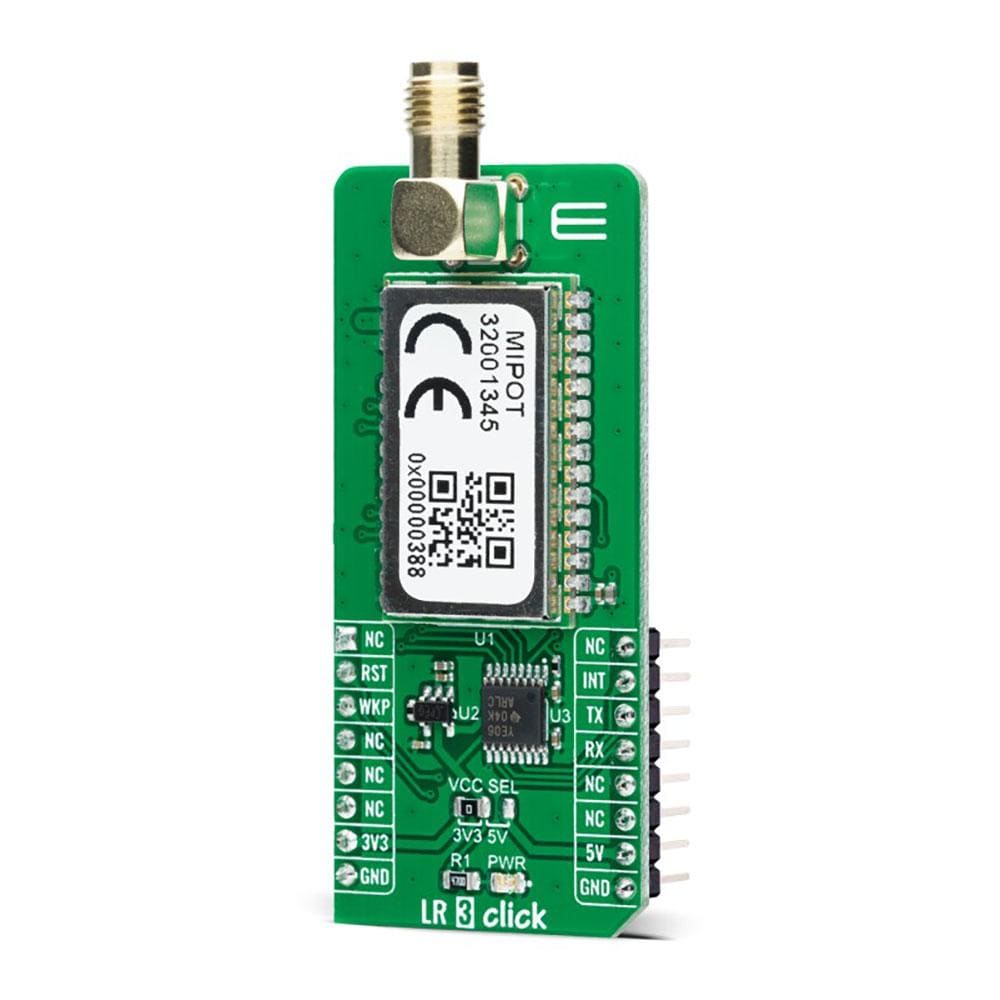
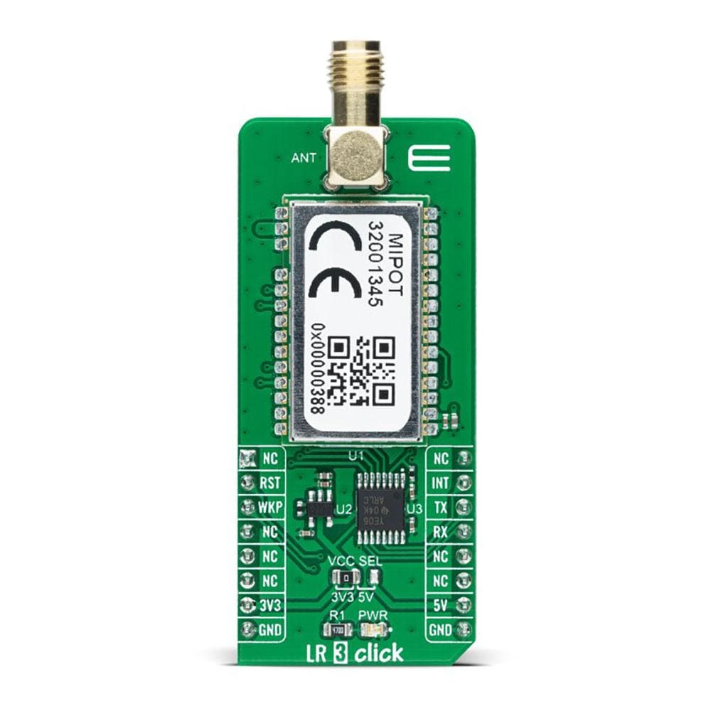
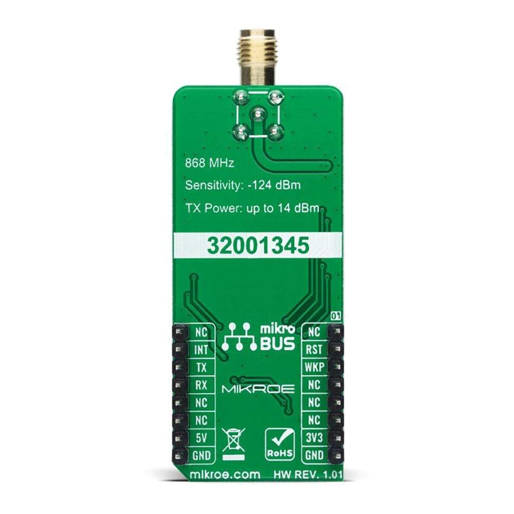
Le LR 3 Click Board™ est une carte complémentaire compacte qui contient un émetteur-récepteur longue portée. Cette carte est équipée de l'émetteur-récepteur SRD 32001345 basé sur la technologie RF, qui fonctionne à une fréquence de 868 MHz de Mipot. Grâce à la fonction de modulation à spectre étalé, ainsi qu'à la faible consommation d'énergie, il est capable d'atteindre une communication longue portée, à l'abri des interférences. Il dispose d'une pile longue portée complète à bord ; il implémente des couches physique, réseau et MAC, permettant un fonctionnement facile via l'interface UART. L'émetteur-récepteur est également certifié RED 2014/53/EU, ce qui permet une intégration facile dans l'application finale. Ce Click Board™ offre une solution simple et fiable pour développer des réseaux IoT longue portée hautement intégrés, des systèmes de sécurité, des réseaux d'alarme et des applications similaires qui nécessitent des solutions de mise en réseau simples et fiables.
Le LR 3 Click Board™ est pris en charge par une bibliothèque compatible mikroSDK, qui comprend des fonctions qui simplifient le développement logiciel. Cette Click Board™ est un produit entièrement testé, prêt à être utilisé sur un système équipé du socket mikroBUS™.
How Does The LR 3 Click Board™ Work?
The LR 3 Click Board™ as its foundation uses the 32001345, a low-power long-range RF technology-based transceiver module from Mipot. It offers a long-range spread spectrum communication with high interference immunity. The network is implemented as a star topology, where endpoints work in duty cycle mode, significantly reducing the overall power consumption. Coupled with the AES128 message encryption and low current consumption, the LR 3 Click Board™ offers an easy and reliable solution for developing low-power, highly integrated IoT networks, security systems, alarm networks, and similar applications that require simple and reliable networking solutions.
The LR 3 Click Board™ can be configured to work as either END or MASTER NODE, by using simple AT commands. While working as the MASTER NODE, the Click board™ can use a set of master-specific commands, such as the pairing command. This command will add the end node which requested pairing, to the master network table. While working as the END NODE, LR 3 Click can issue slave specific commands/requests, such as the pairing request command, which will allow that end node to be paired with the master.
The LR 3 Click Board™ communicates with MCU using the UART interface with commonly used UART RX and TX pins at data rates up to 115200bps for the data transfer. In addition to these features, the 32001345 also uses several GPIO pins connected to the mikroBUS™ socket. The WK pin routed on the CS pin of the mikroBUS™ represents the Wake-up function used for waking up the device, while the RST pin on the mikroBUS™ socket can perform Hardware Reset function by putting this pin in a logic low state. This Click board™ also has an indicator routed on the INT pin of the mikroBUS ™ socket, which will provide the user with feedback after a successfully received package and verified checksum.
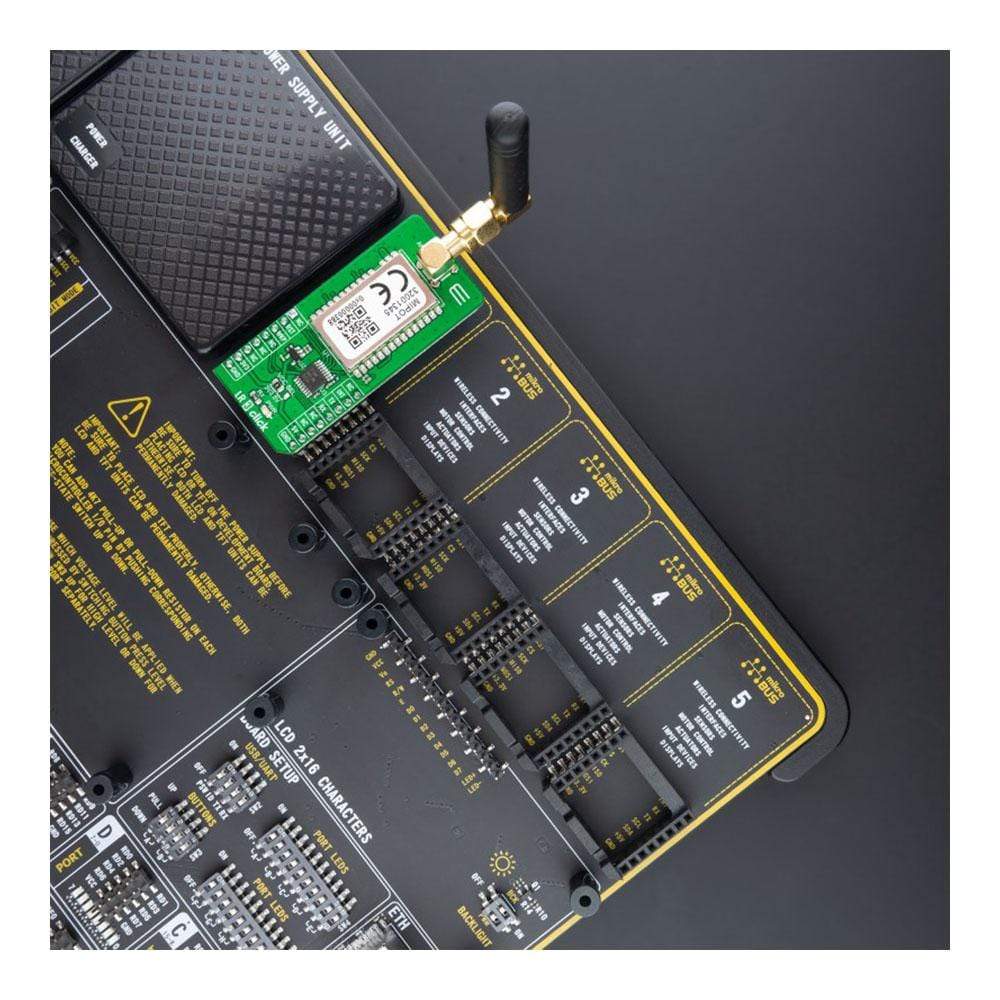
The LR 3 Click Board™ features the SMA antenna connector with an impedance of 50Ω, so it can be equipped with the appropriate 868MHz compliant antenna that MikroE has in its offer.
The LR 3 Click Board™ can operate with both 3.3V and 5V logic voltage levels selected via the VCC SEL jumper. A proper logic voltage level conversion is performed by the TXB0106 voltage level shifter, while the LDO ensures that recommended values power the module. This allows for both 3.3V and 5V capable MCUs to use the UART communication lines properly. However, the Click board™ comes equipped with a library containing easy-to-use functions and an example code that can be used, as a reference, for further development.
SPECIFICATIONS
Type | LoRa |
Applications | The LR 3 Click Board™ offers an easy and reliable solutions for developing low power, highly integrated IoT networks, security systems, alarm networks, and similar applications that require simple and reliable networking solutions |
On-board modules | MIPOT 32001345, Lora® RF technology-based long range transceiver |
Key Features | The click board™ features robust Lora® RF technology based wireless networking, full network stack, message encrypting (AES128), easy to use UART interface and low power consumption |
Interface | UART |
Compatibility | mikroBUS |
Click board size | L (57.15 x 25.4 mm) |
Input Voltage | 3.3V or 5V |
PINOUT DIAGRAM
This table shows how the pinout of the LR 3 Click Board™ corresponds to the pinout on the mikroBUS™ socket (the latter shown in the two middle columns).
Notes | Pin | Pin | Notes | ||||
---|---|---|---|---|---|---|---|
NC | 1 | AN | PWM | 16 | NC | ||
Reset | RST | 2 | RST | INT | 15 | INT | Data TX indication |
Wake up | WKP | 3 | CS | RX | 14 | TX | UART TX |
NC | 4 | SCK | TX | 13 | RX | UART RX | |
NC | 5 | MISO | SCL | 12 | NC | ||
NC | 6 | MOSI | SDA | 11 | NC | ||
Power supply | +3.3V | 7 | 3.3V | 5V | 10 | +5V | Power supply |
Ground | GND | 8 | GND | GND | 9 | GND | Ground |
ONBOARD SETTINGS AND INDICATORS
Label | Name | Default | Description |
---|---|---|---|
LD1 | PWR | - | Power LED indicator |
JP1 | VCC SEL | Left | Logic Level Voltage Selection 3V3/5V: Left position 3V3, Right position 5V |
LR 3 CLICK ELECTRICAL SPECIFICATIONS
Description | Min | Typ | Max | Unit |
---|---|---|---|---|
Supply Voltage | 3.3 | - | 5 | V |
Operating Frequency Range | 863 | 868 | 870 | MHz |
Operating Temperature Range | -40 | +25 | +85 | °C |
Software Support
We provide a library for the LR 3 Click Board™ as well as a demo application (example), developed using MikroElektronika compilers. The demo can run on all the main MikroElektronika development boards.
The package can be downloaded/installed directly form compilers IDE(recommended way), or downloaded from our LibStock, or found on mikroE Github account.
Library Description
This library contains API for LR 3 Click driver.
Key Functions
void lr3_cfg_setup ( lr3_cfg_t *cfg );
- Config Object Initialization function.LR3_RETVAL lr3_init ( lr3_t *ctx, lr3_cfg_t *cfg );
- Initialization function.
Example Description
This example reads and processes data from LR 3 clicks.
The demo application is composed of two sections :
void application_task ( void ) { #ifdef END_NODE strcpy( tmp_msg.payload, TEXT_TO_SEND ); lr3_tx_msg.data_in = &tmp_msg.payload[ 0 ]; lr3_tx_msg.n_bytes = strlen( TEXT_TO_SEND ); lr3_tx_msg.destination_id = LR3_BROADCAST_MESSAGE; lr3_tx_msg.option = LR3_UNCONFIRMED_DATA_TX; if ( lr3_tx_message( &lr3, &lr3_tx_msg ) == 0 ) { log_printf( &logger, "Message: "%s" sent to MASTER...rn", ( uint8_t * ) TEXT_TO_SEND ); log_printf( &logger, "------------------------rn" ); } Delay_ms( 3000 ); #endif #ifdef MASTER lr3_read_message_process( &lr3 ); #endif }
The full application code, and ready to use projects can be installed directly form compilers IDE(recommneded) or found on LibStock page or mikroE GitHub accaunt.
Other mikroE Libraries used in the example:
- MikroSDK.Board
- MikroSDK.Log
- Click.LR3
Additional Notes and Information
Depending on the development board you are using, you may need USB UART click, USB UART 2 click or RS232 click to connect to your PC, for development systems with no UART to USB interface available on the board. The terminal available in all MikroElektronika compilers, or any other terminal application of your choice, can be used to read the message.
MIKROSDK
The LR 3 Click Board™ is supported with mikroSDK - MikroElektronika Software Development Kit. To ensure proper operation of mikroSDK compliant Click board™ demo applications, mikroSDK should be downloaded from the LibStock and installed for the compiler you are using.
Tableau à clic LR 3
Frequently Asked Questions
Have a Question?
Be the first to ask a question about this.