


Mikroelektronika d.o.o.
Carte de commande LED 9 Click
Carte de commande LED 9 Click
SKU: MIKROE-4595
Impossible de charger la disponibilité du service de retrait

Key Features
Overview
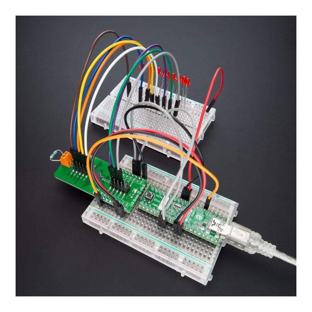
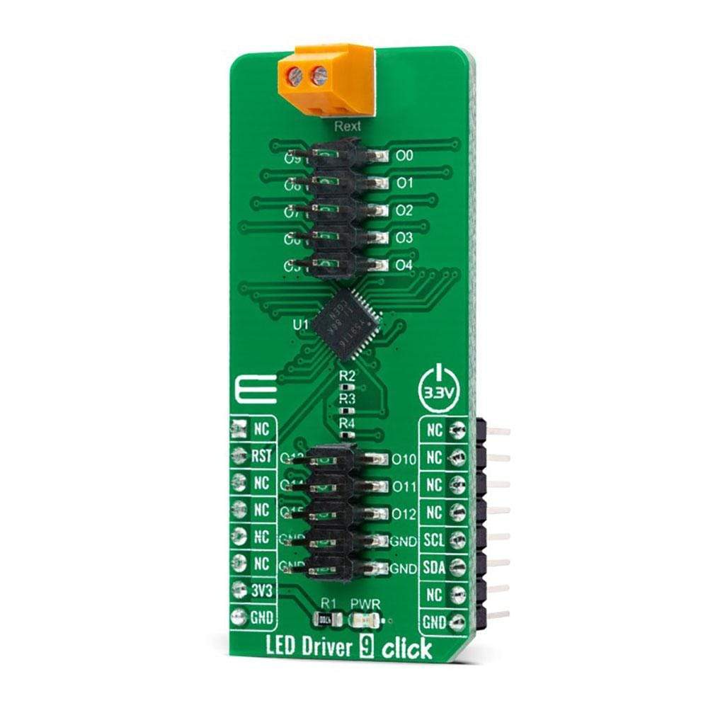
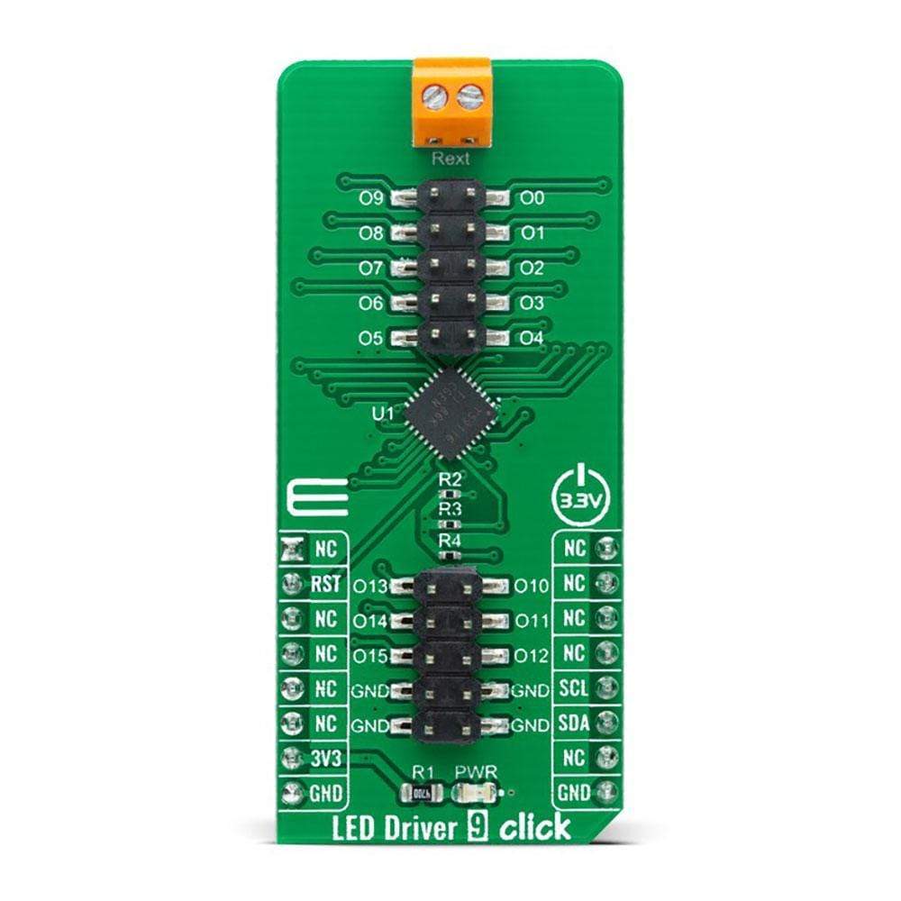
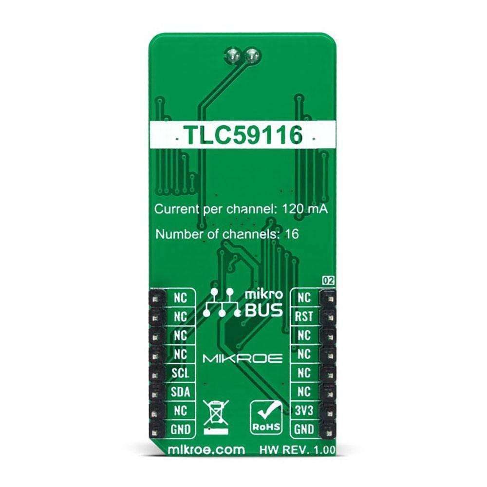
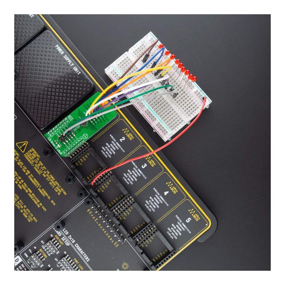
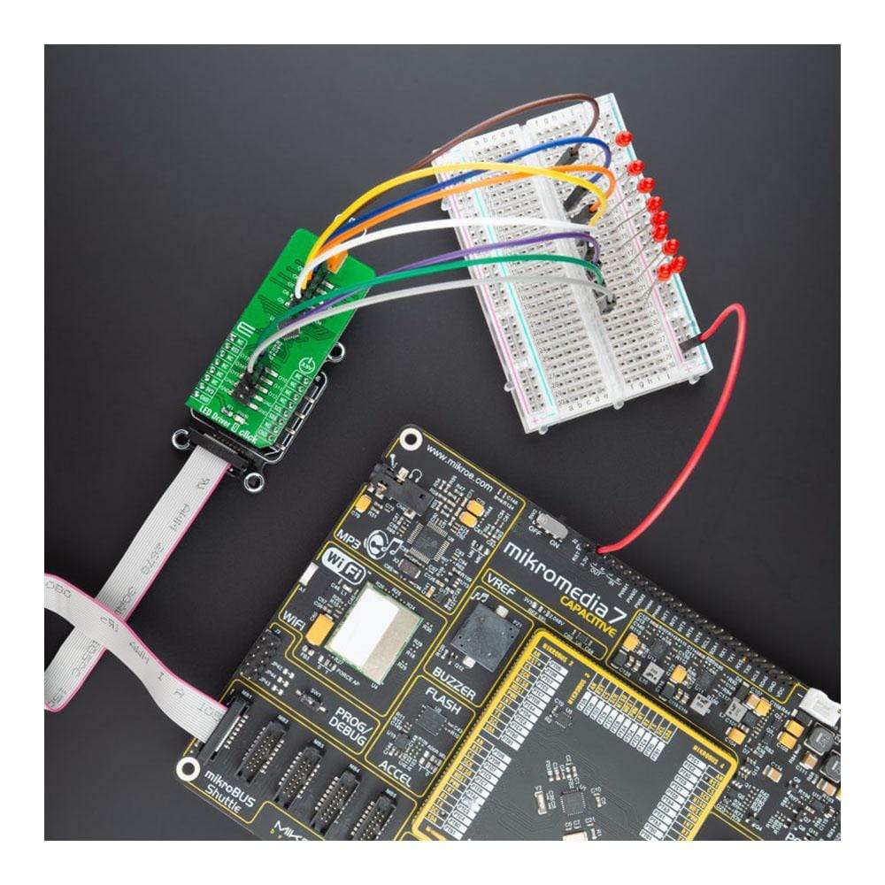
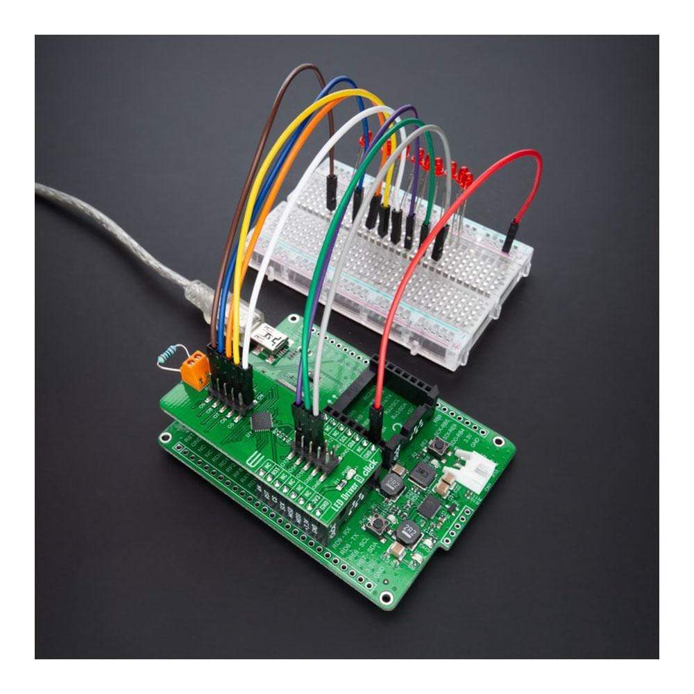
The LED Driver 9 Click Board™ is a compact add-on board that simplifies the control of multiple LEDs. This board features the TLC59116, I2C bus-controlled 16-channel LED driver optimized for red/green/blue/amber (RGBA) colour mixing and backlight application from Texas Instruments. Each 16-channel LED output has its 8-bit resolution (256 steps), fixed-frequency, individual PWM controller that operates at 97 kHz, with a duty cycle that is adjustable from 0% to 99.6%. The PWM controller allows each LED to be set to a specific brightness value and dims or blinks all LEDs with the same value. This Click Board™ is suitable for RGBA colour mixing and backlight application for amusement products, LED status signalization, home automation projects, industrial equipment, and many more.
The LED Driver 9 Click Board™ is supported by a mikroSDK compliant library, which includes functions that simplify software development. This Click Board™ comes as a fully tested product, ready to be used on a system equipped with the mikroBUS™ socket.
Downloads
Le LED Driver 9 Click Board™ est une carte complémentaire compacte qui simplifie le contrôle de plusieurs LED. Cette carte comprend le pilote LED TLC59116 à 16 canaux contrôlé par bus I2C optimisé pour le mélange de couleurs rouge/vert/bleu/ambre (RGBA) et l'application de rétroéclairage de Texas Instruments. Chaque sortie LED à 16 canaux possède sa résolution 8 bits (256 étapes), sa fréquence fixe, son contrôleur PWM individuel qui fonctionne à 97 kHz, avec un cycle de service réglable de 0 % à 99,6 %. Le contrôleur PWM permet de régler chaque LED sur une valeur de luminosité spécifique et d'atténuer ou de faire clignoter toutes les LED ayant la même valeur. Ce Click Board™ convient au mélange de couleurs RGBA et à l'application de rétroéclairage pour les produits de divertissement, la signalisation d'état des LED, les projets domotiques, les équipements industriels et bien d'autres.
Le pilote LED 9 Click Board™ est pris en charge par une bibliothèque compatible mikroSDK, qui comprend des fonctions qui simplifient le développement logiciel. Cette Click Board™ est un produit entièrement testé, prêt à être utilisé sur un système équipé du socket mikroBUS™.
| General Information | |
|---|---|
Part Number (SKU) |
MIKROE-4595
|
Manufacturer |
|
| Physical and Mechanical | |
Weight |
0.02 kg
|
| Other | |
EAN |
8606027382550
|
Frequently Asked Questions
Have a Question?
Be the first to ask a question about this.