


Mikroelektronika d.o.o.
Carte à clic ADC 11
Carte à clic ADC 11
SKU: MIKROE-4593
Impossible de charger la disponibilité du service de retrait


Key Features
Overview
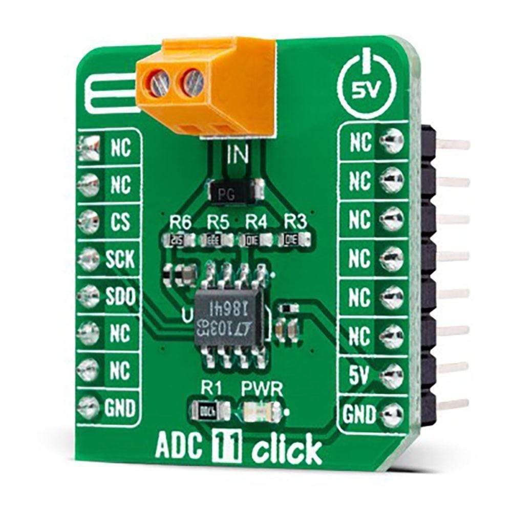
The ADC 11 Click Board™ is a compact add-on board that contains a high-performance data converter. This board features the LTC1864, a 16-bit 250ksps analogue-to-digital converter from Analog Devices. With a typical supply current only 850µA at the maximum sampling frequency, the LTC1864 is among the lowest power consumption ADCs available. After conversion, the LTC1864 goes into a low-power Sleep mode, further reducing the supply current. That’s why it can run at proper micro-power levels in applications that do not require the maximum sampling rate of the LTC1864. This Click Board™ is suitable for high-speed data acquisition, low power battery-operated instrumentation, isolated and remote data acquisition, and many other applications.
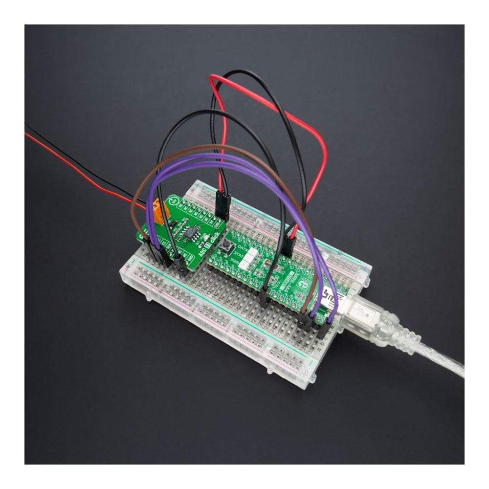
The ADC 11 Click Board™ is supported by a mikroSDK compliant library, which includes functions that simplify software development. This Click Board™ comes as a fully tested product, ready to be used on a system equipped with the mikroBUS™ socket.
Downloads
L' ADC 11 Click Board™ est une carte complémentaire compacte qui contient un convertisseur de données hautes performances. Cette carte comprend le LTC1864, un convertisseur analogique-numérique 16 bits 250 kps d'Analog Devices. Avec un courant d'alimentation typique de seulement 850 µA à la fréquence d'échantillonnage maximale, le LTC1864 fait partie des ADC à plus faible consommation d'énergie disponibles. Après la conversion, le LTC1864 passe en mode veille à faible consommation, réduisant encore le courant d'alimentation. C'est pourquoi il peut fonctionner à des niveaux de micro-puissance appropriés dans les applications qui ne nécessitent pas la fréquence d'échantillonnage maximale du LTC1864. Cette Click Board™ convient à l'acquisition de données à grande vitesse, à l'instrumentation alimentée par batterie à faible consommation, à l'acquisition de données isolées et à distance, et à de nombreuses autres applications.
La carte à clic ADC 11™ est pris en charge par une bibliothèque compatible mikroSDK, qui comprend des fonctions qui simplifient le développement logiciel. Cette Click Board™ est un produit entièrement testé, prêt à être utilisé sur un système équipé du socket mikroBUS™.
| General Information | |
|---|---|
Part Number (SKU) |
MIKROE-4593
|
Manufacturer |
|
| Physical and Mechanical | |
Weight |
0.02 kg
|
| Other | |
EAN |
8606027382482
|
Frequently Asked Questions
Have a Question?
Be the first to ask a question about this.