


Mikroelektronika d.o.o.
Carte à clic pour décodeur DTMF
Carte à clic pour décodeur DTMF
SKU: MIKROE-4579
Impossible de charger la disponibilité du service de retrait
Overview
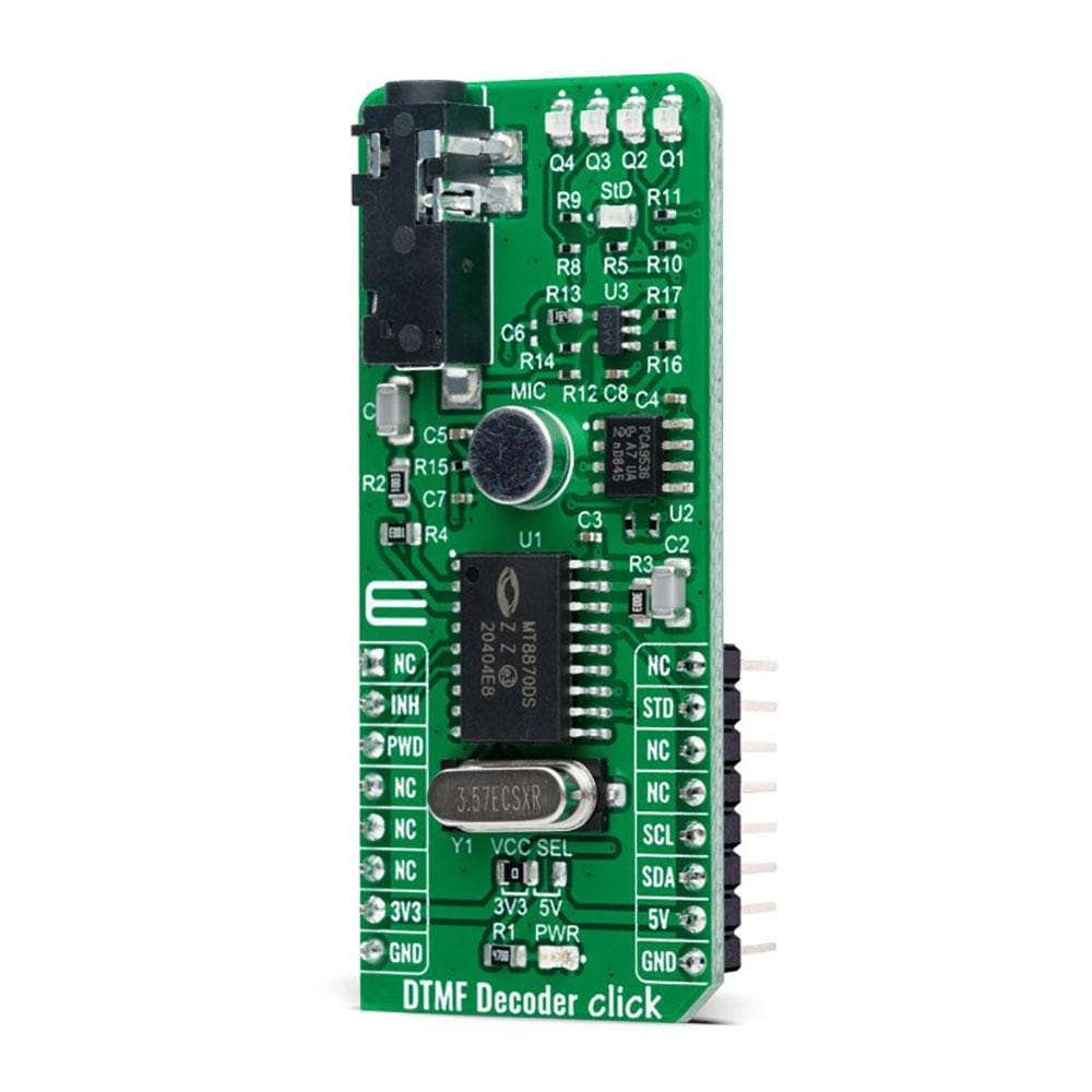
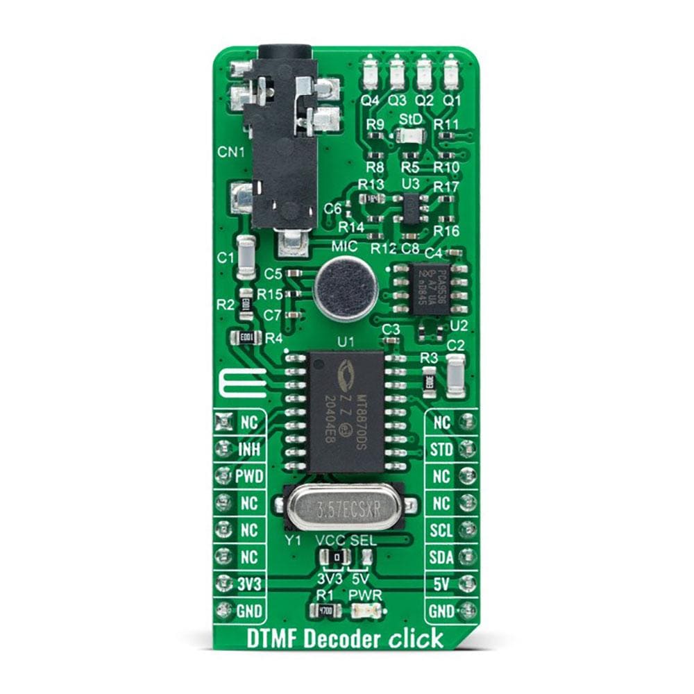
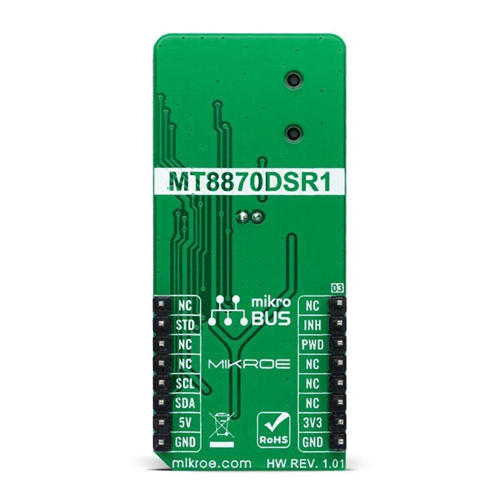
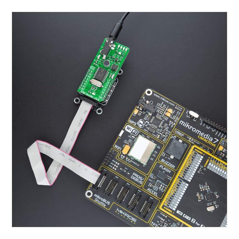
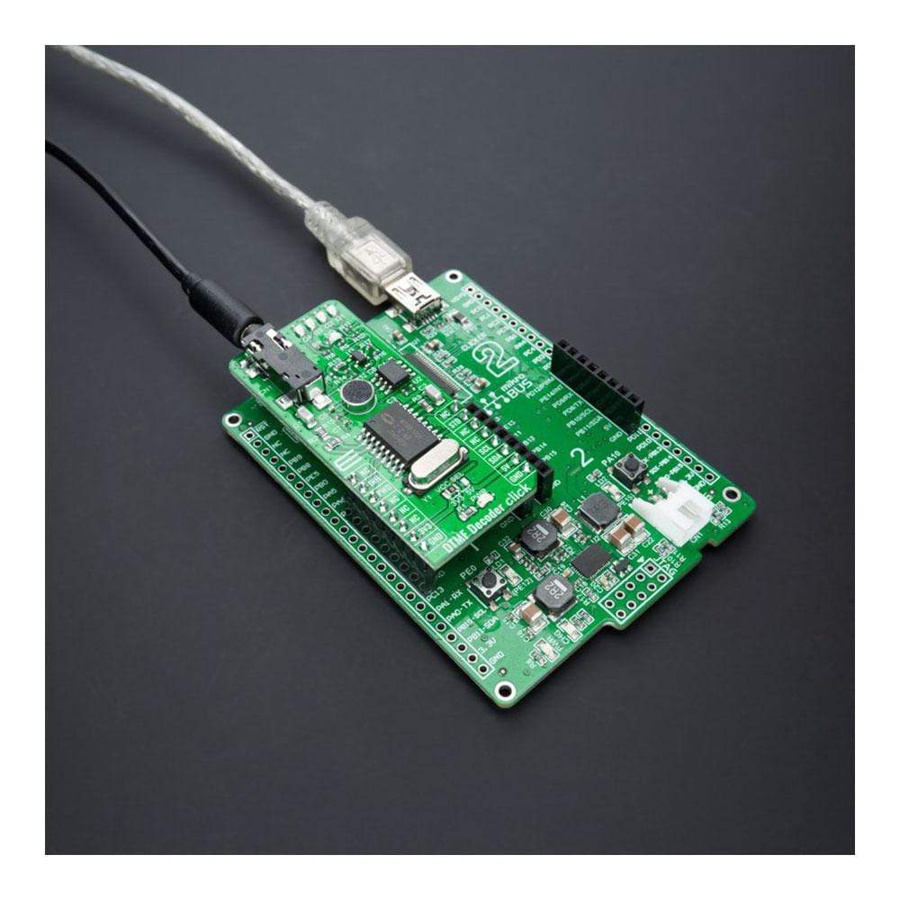
The DTMF Decoder Click Board™ is a compact add-on board that contains an integrated DTMF receiver with enhanced sensitivity. This board features the MT8870D, a complete DTMF receiver integrating the band-split filter and digital decoder functions from Microchip Technology. It offers low power consumption and high performance and uses digital counting techniques to detect and decode all 16 DTMF tone-pairs into a 4-bit code. Whenever a valid tone is detected, it outputs the associated value in binary on four LEDs, with an additional indicator that strobes after each new tone. This Click Board™ is suitable for paging systems, remote control, electronic communications circuits, and various other applications.
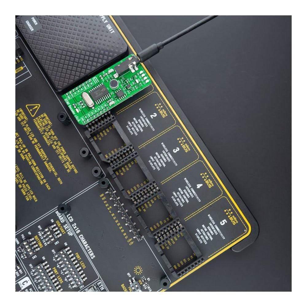
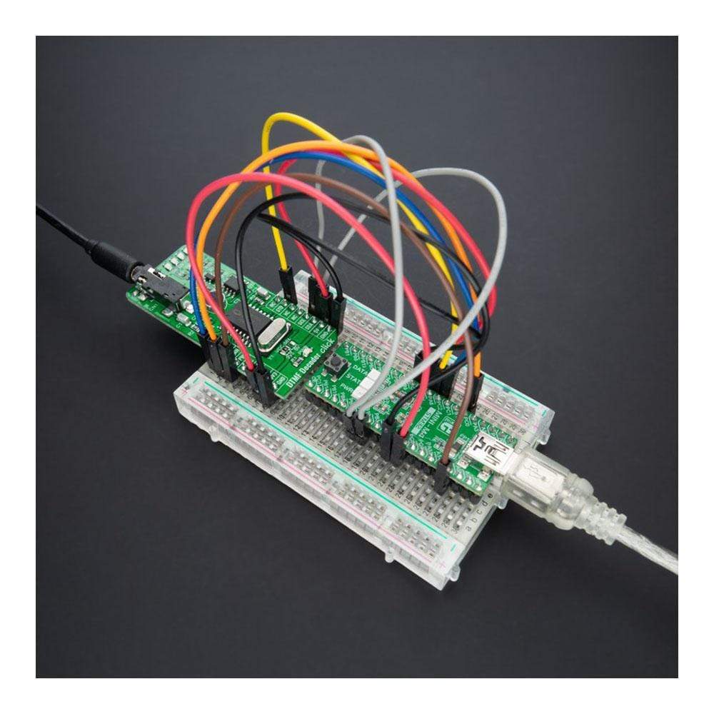
The DTMF Decoder Click Board™ is supported by a mikroSDK compliant library, which includes functions that simplify software development. This Click Board™ comes as a fully tested product, ready to be used on a system equipped with the mikroBUS™ socket.
Downloads
Le Le décodeur DTMF Click Board™ est une carte complémentaire compacte qui contient un récepteur DTMF intégré avec une sensibilité améliorée. Cette carte comprend le MT8870D, un récepteur DTMF complet intégrant le filtre à division de bande et les fonctions de décodeur numérique de Microchip Technology. Il offre une faible consommation d'énergie et des performances élevées et utilise des techniques de comptage numérique pour détecter et décoder les 16 paires de tonalités DTMF en un code à 4 bits. Chaque fois qu'une tonalité valide est détectée, il génère la valeur associée en binaire sur quatre LED, avec un indicateur supplémentaire qui clignote après chaque nouvelle tonalité. Ce Click Board™ convient aux systèmes de radiomessagerie, à la télécommande, aux circuits de communication électronique et à diverses autres applications.
Le décodeur DTMF Click Board™ est pris en charge par une bibliothèque compatible mikroSDK, qui comprend des fonctions qui simplifient le développement logiciel. Ce Click Board™ est un produit entièrement testé, prêt à être utilisé sur un système équipé de la prise mikroBUS™.
| General Information | |
|---|---|
Part Number (SKU) |
MIKROE-4579
|
Manufacturer |
|
| Physical and Mechanical | |
Weight |
0.021 kg
|
| Other | |
EAN |
8606027382291
|
Frequently Asked Questions
Have a Question?
Be the first to ask a question about this.