


Mikroelektronika d.o.o.
Carte Power MUX 2 Click
Carte Power MUX 2 Click
SKU: MIKROE-4575
Impossible de charger la disponibilité du service de retrait
Overview
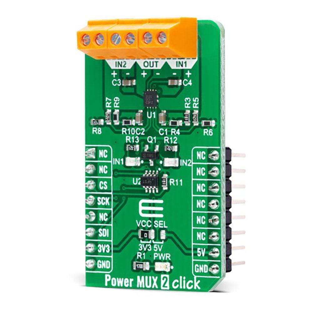
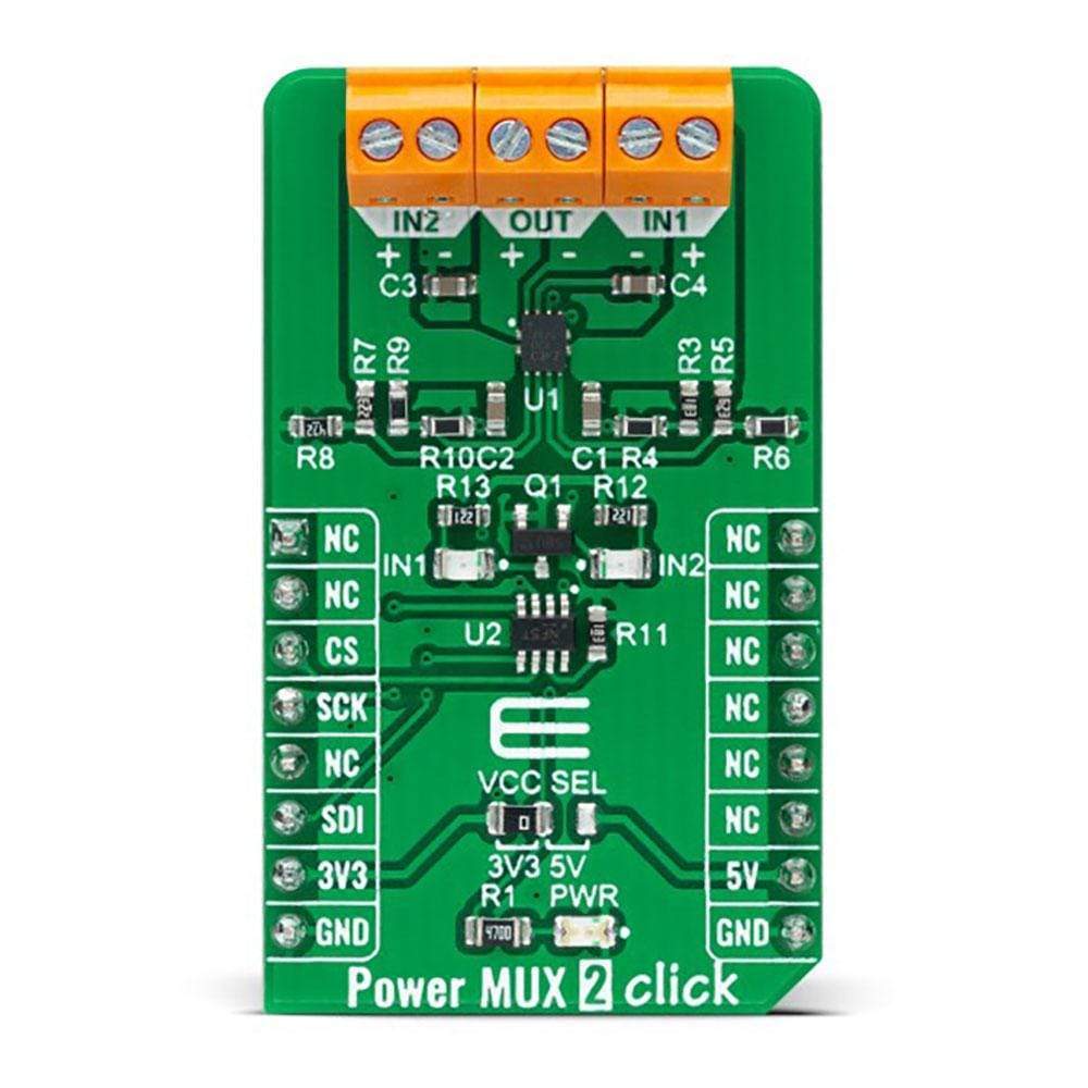
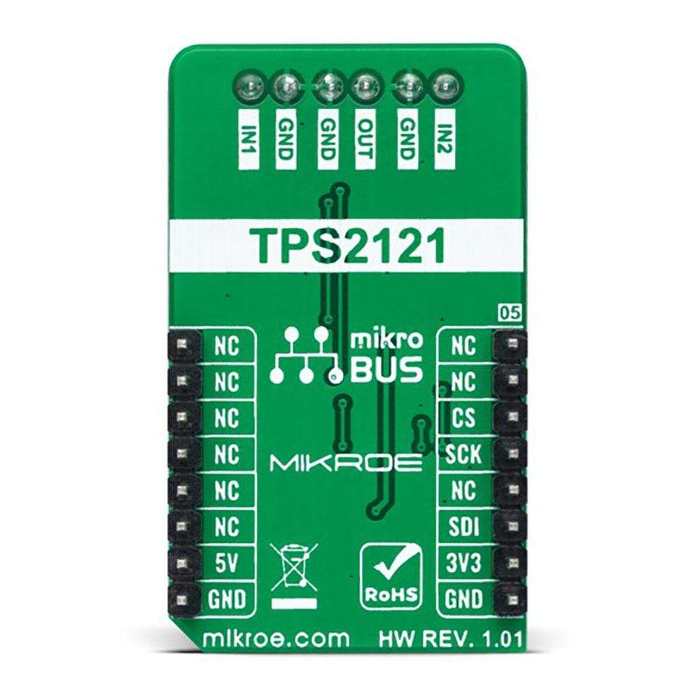
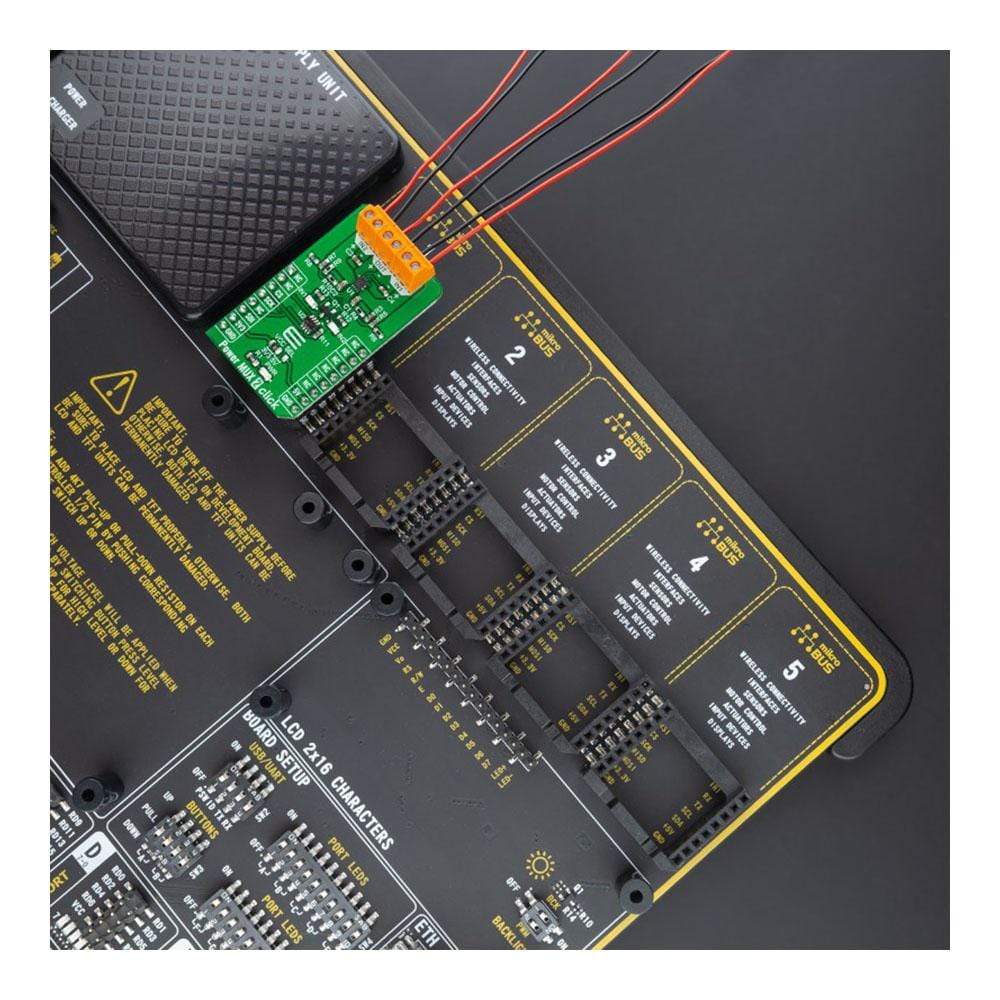
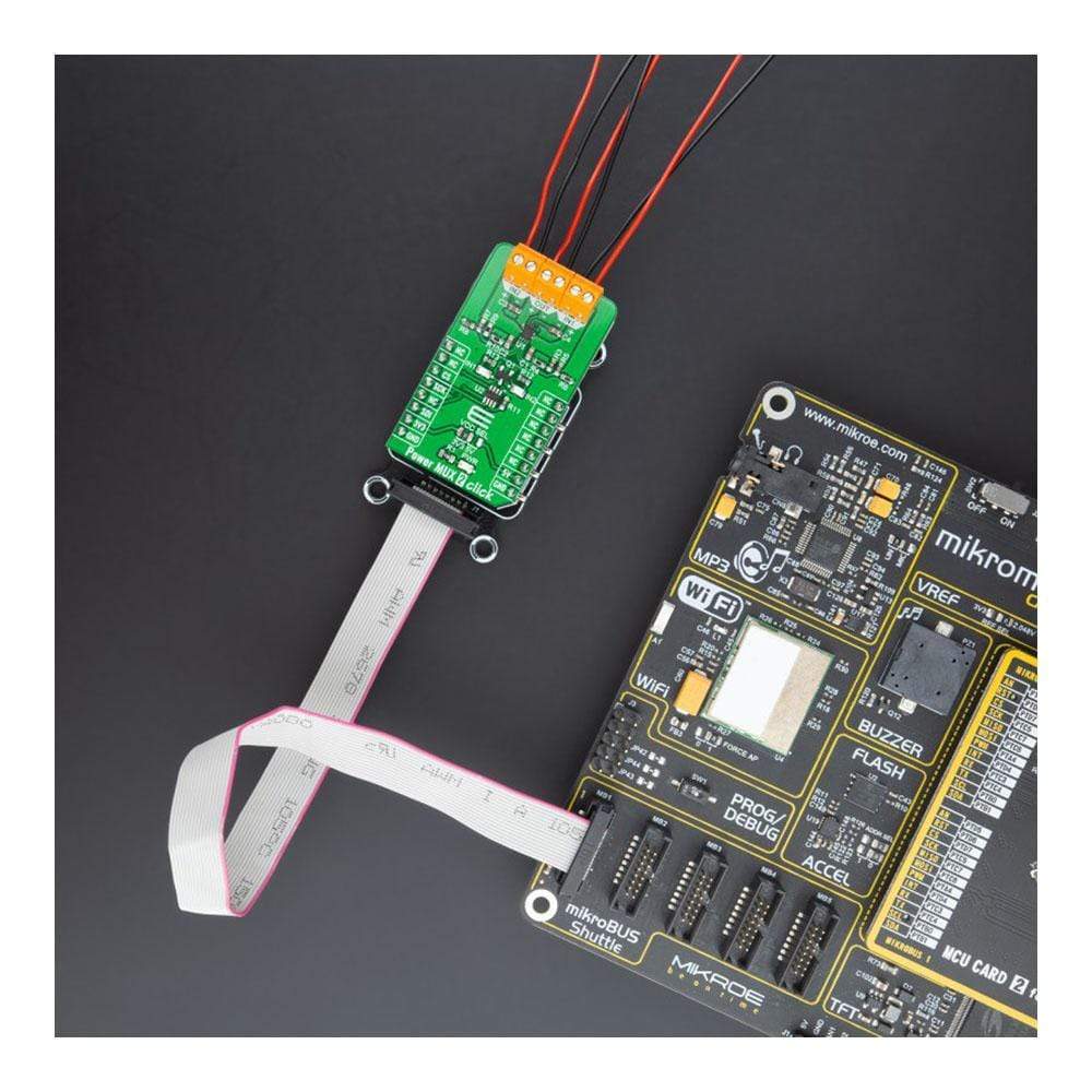
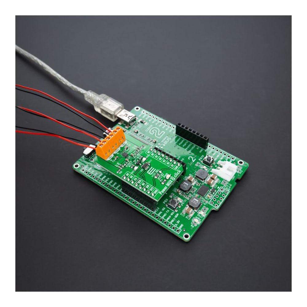
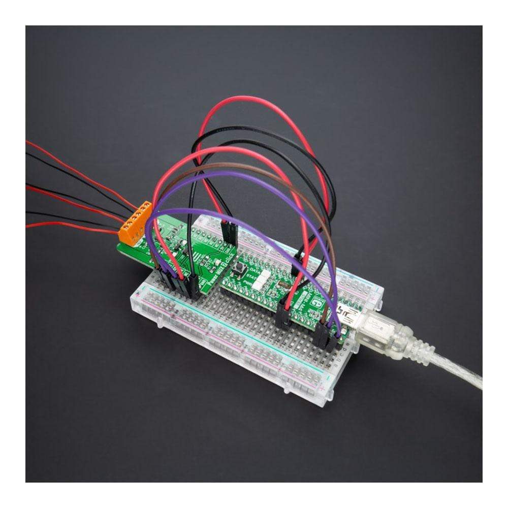
The Power MUX 2 Click Board™ is a compact add-on board with a highly configurable power mux. This board features the TPS2120, a dual-input single-output power multiplexer with an automatic switchover feature from Texas Instruments. This Click Board™ prioritises the main supply when present and quickly switches to auxiliary supply when the main supply drops. During switchover, the voltage drop is controlled to block reverse current before it happens and provide uninterrupted power to the load with minimal hold-up capacitance. This Click Board™ is suitable for backup and standby power applications, input source selection, and various systems having multiple power sources.
The Power MUX 2 Click Board™ is supported by a mikroSDK compliant library, which includes functions that simplify software development. This Click Board™ comes as a thoroughly tested product, ready to be used on a system equipped with the mikroBUS™ socket.
Downloads
Le Power MUX 2 Click Board™ est une carte complémentaire compacte dotée d'un multiplexeur de puissance hautement configurable. Cette carte est équipée du TPS2120, un multiplexeur de puissance à double entrée et sortie unique avec une fonction de commutation automatique de Texas Instruments. Cette carte Click Board™ donne la priorité à l'alimentation principale lorsqu'elle est présente et bascule rapidement vers l'alimentation auxiliaire lorsque l'alimentation principale chute. Pendant la commutation, la chute de tension est contrôlée pour bloquer le courant inverse avant qu'il ne se produise et fournir une alimentation ininterrompue à la charge avec une capacité de maintien minimale. Cette carte Click Board™ convient aux applications d'alimentation de secours et de veille, à la sélection de la source d'entrée et à divers systèmes dotés de plusieurs sources d'alimentation.
La carte Power MUX 2 Click Board™ est pris en charge par une bibliothèque compatible mikroSDK, qui comprend des fonctions qui simplifient le développement logiciel. Cette Click Board™ est un produit entièrement testé, prêt à être utilisé sur un système équipé du socket mikroBUS™.
| General Information | |
|---|---|
Part Number (SKU) |
MIKROE-4575
|
Manufacturer |
|
| Physical and Mechanical | |
Weight |
0.019 kg
|
| Other | |
EAN |
8606027382246
|
Frequently Asked Questions
Have a Question?
Be the first to ask a question about this.