


Mikroelektronika d.o.o.
Carte à clic CAN FD 6
Carte à clic CAN FD 6
SKU: MIKROE-4572
Impossible de charger la disponibilité du service de retrait
Key Features
Overview
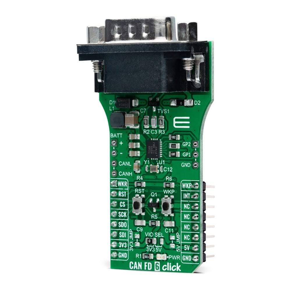
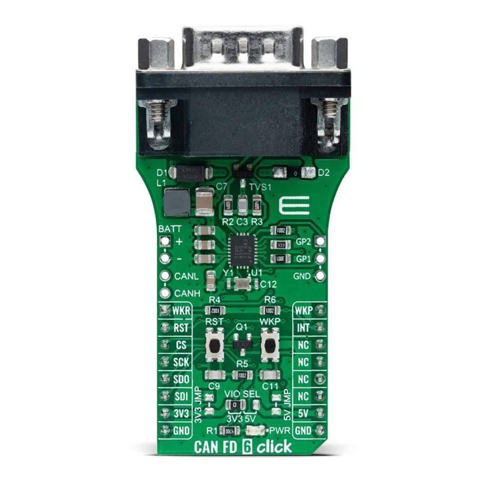
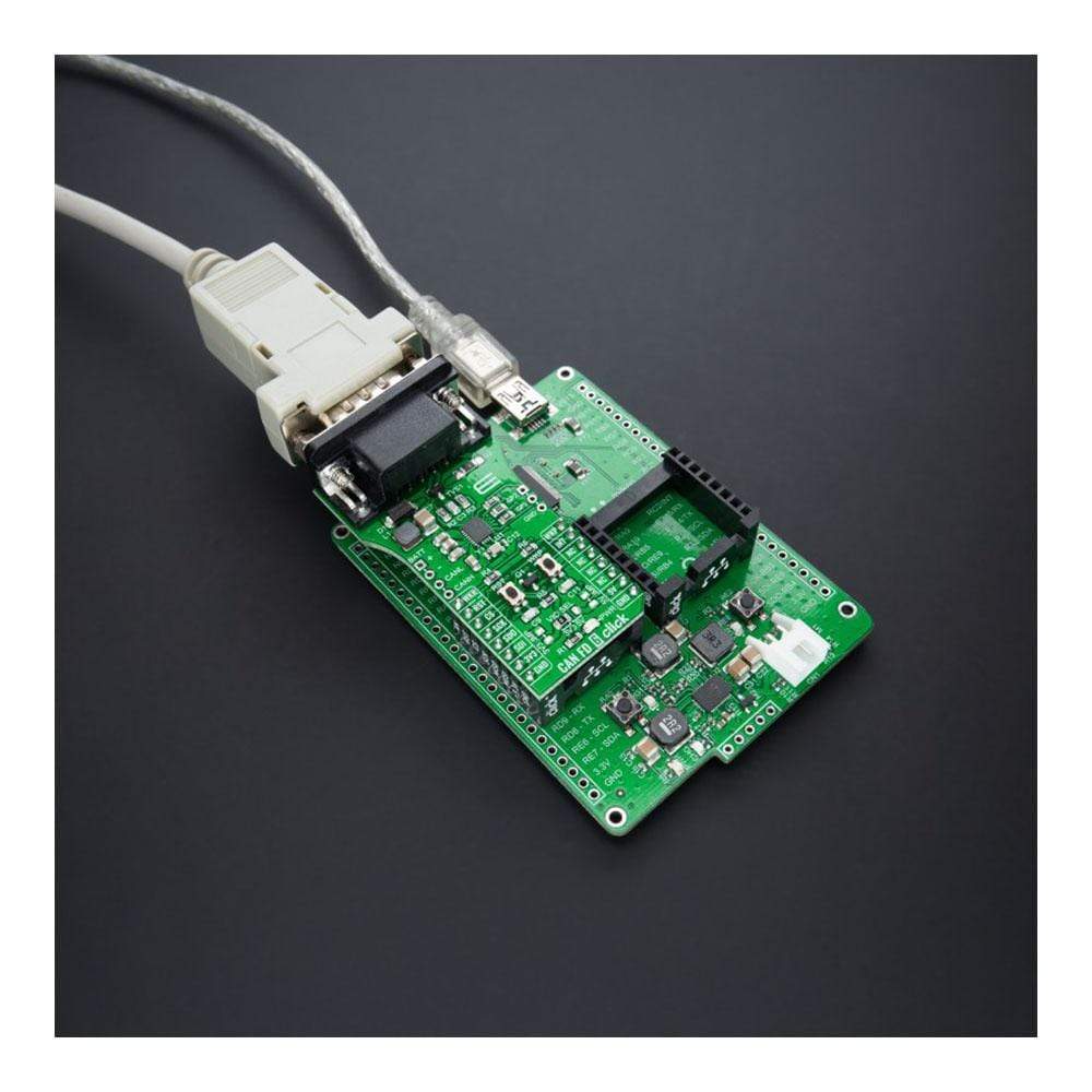
Enhance your automotive and industrial applications with the CAN FD 6 Click Board™. This compact add-on board integrates a high-performance CAN transceiver supporting Controller Area Network (CAN) and Controller Area Network Flexible Data-Rate (CAN FD) protocols. Developed with the TCAN4550 CAN FD controller from Texas Instruments, this board enables data rates of up to 5 megabits per second (Mbps).
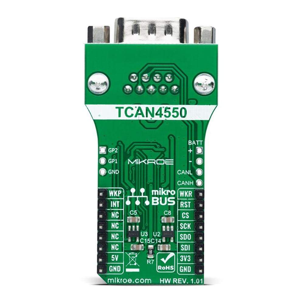
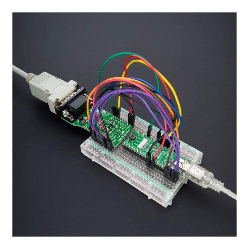
The CAN FD 6 Click Board™ offers high-bandwidth capabilities and data-rate flexibility, bridging the gap between the CAN bus and the system processor seamlessly through an SPI interface. It not only supports classical CAN and CAN FD but also features wake-up functionality, allowing for local and bus wake using the CAN bus.
- High-speed CAN networking made easy for automotive and industrial settings.
- Low-power mode with wake-up capabilities via the CAN bus ensures efficient energy consumption.
This Click Board™ is the perfect solution for applications where reliable high-speed communication is essential combined with a need for power efficiency. Additionally, the board is supported by a mikroSDK compliant library, providing developers with simplified software development functions.
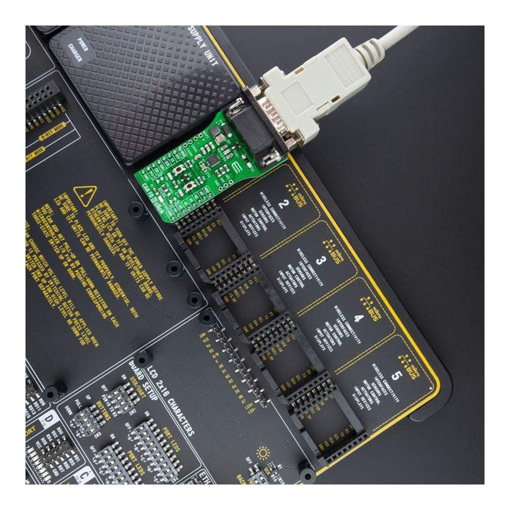
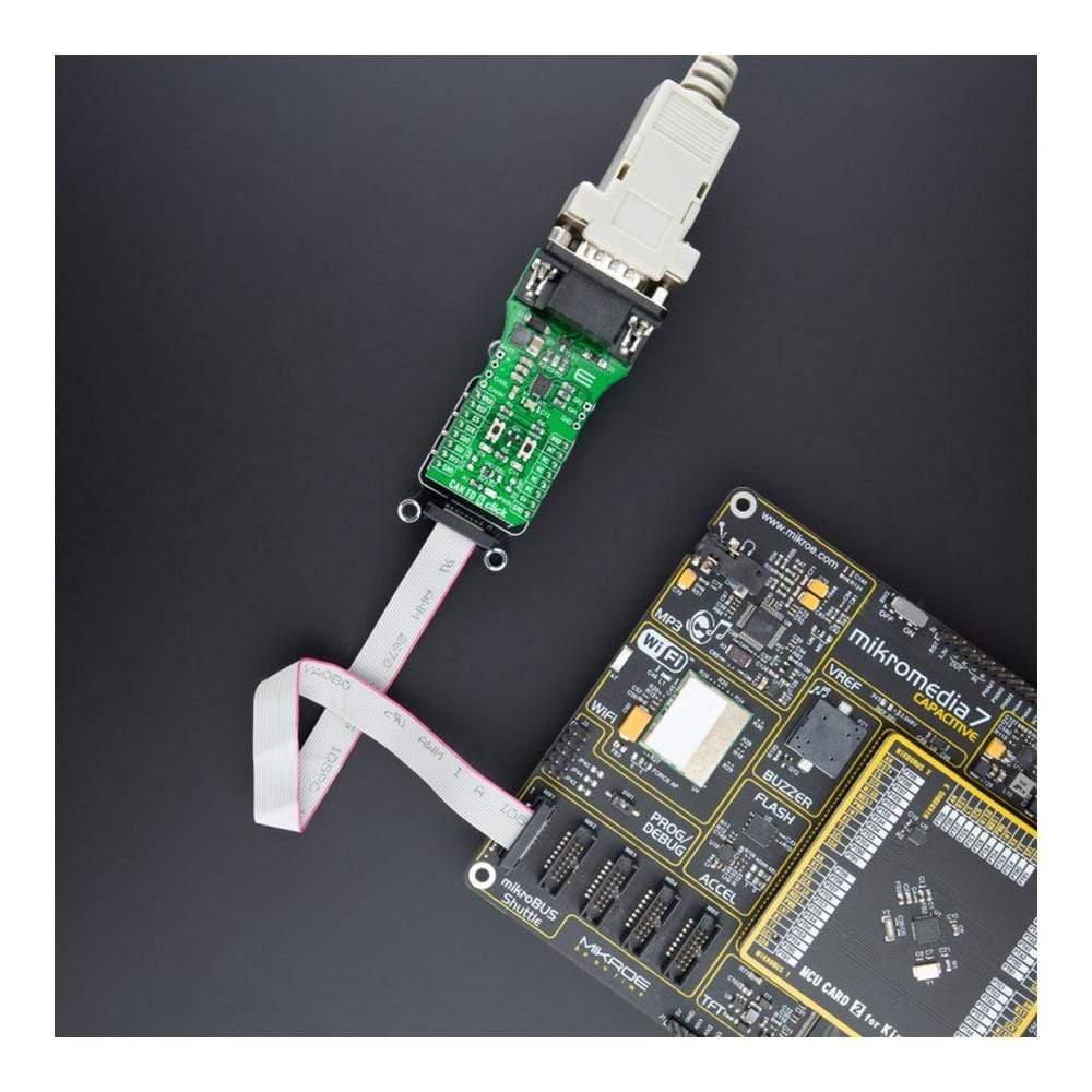
Tested thoroughly to ensure reliability, the CAN FD 6 Click Board™ is ready to be integrated into systems equipped with a mikroBUS™ socket. Experience seamless data transfer and efficient power management with this advanced add-on board.
Downloads
Améliorez vos applications automobiles et industrielles avec la carte Click Board™ CAN FD 6. Cette carte complémentaire compacte intègre un émetteur-récepteur CAN hautes performances prenant en charge les protocoles Controller Area Network (CAN) et Controller Area Network Flexible Data-Rate (CAN FD). Développée avec le contrôleur CAN FD TCAN4550 de Texas Instruments, cette carte permet des débits de données allant jusqu'à 5 mégabits par seconde (Mbps).
La carte CAN FD 6 Click Board™ offre des capacités de bande passante élevée et une flexibilité de débit de données, comblant de manière transparente l'écart entre le bus CAN et le processeur système via une interface SPI. Elle prend non seulement en charge les CAN et CAN FD classiques, mais dispose également d'une fonctionnalité de réveil, permettant un réveil local et par bus à l'aide du bus CAN.
- La mise en réseau CAN haut débit simplifiée pour les environnements automobiles et industriels.
- Le mode basse consommation avec fonctions de réveil via le bus CAN garantit une consommation d'énergie efficace.
Cette carte Click Board™ est la solution idéale pour les applications où une communication fiable à haut débit est essentielle, tout en nécessitant une efficacité énergétique. De plus, la carte est prise en charge par une bibliothèque compatible mikroSDK, offrant aux développeurs des fonctions de développement logiciel simplifiées.
Testé minutieusement pour garantir sa fiabilité, le CAN FD 6 Click Board™ est prêt à être intégré dans des systèmes équipés d'une prise mikroBUS™. Bénéficiez d'un transfert de données fluide et d'une gestion efficace de l'alimentation avec cette carte complémentaire avancée.
| General Information | |
|---|---|
Part Number (SKU) |
MIKROE-4572
|
Manufacturer |
|
| Physical and Mechanical | |
Weight |
0.02 kg
|
| Other | |
EAN |
5055383601196
|
Frequently Asked Questions
Have a Question?
Be the first to ask a question about this.