


Mikroelektronika d.o.o.
Carte Click ATA6571
Carte Click ATA6571
SKU: MIKROE-4381
Impossible de charger la disponibilité du service de retrait


Key Features
Overview
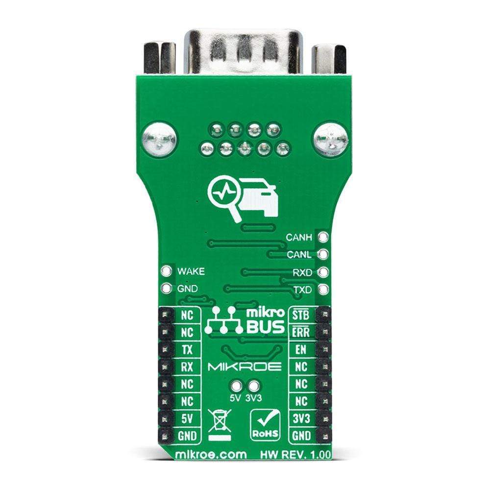
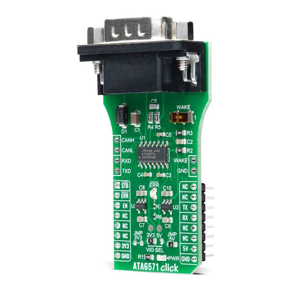
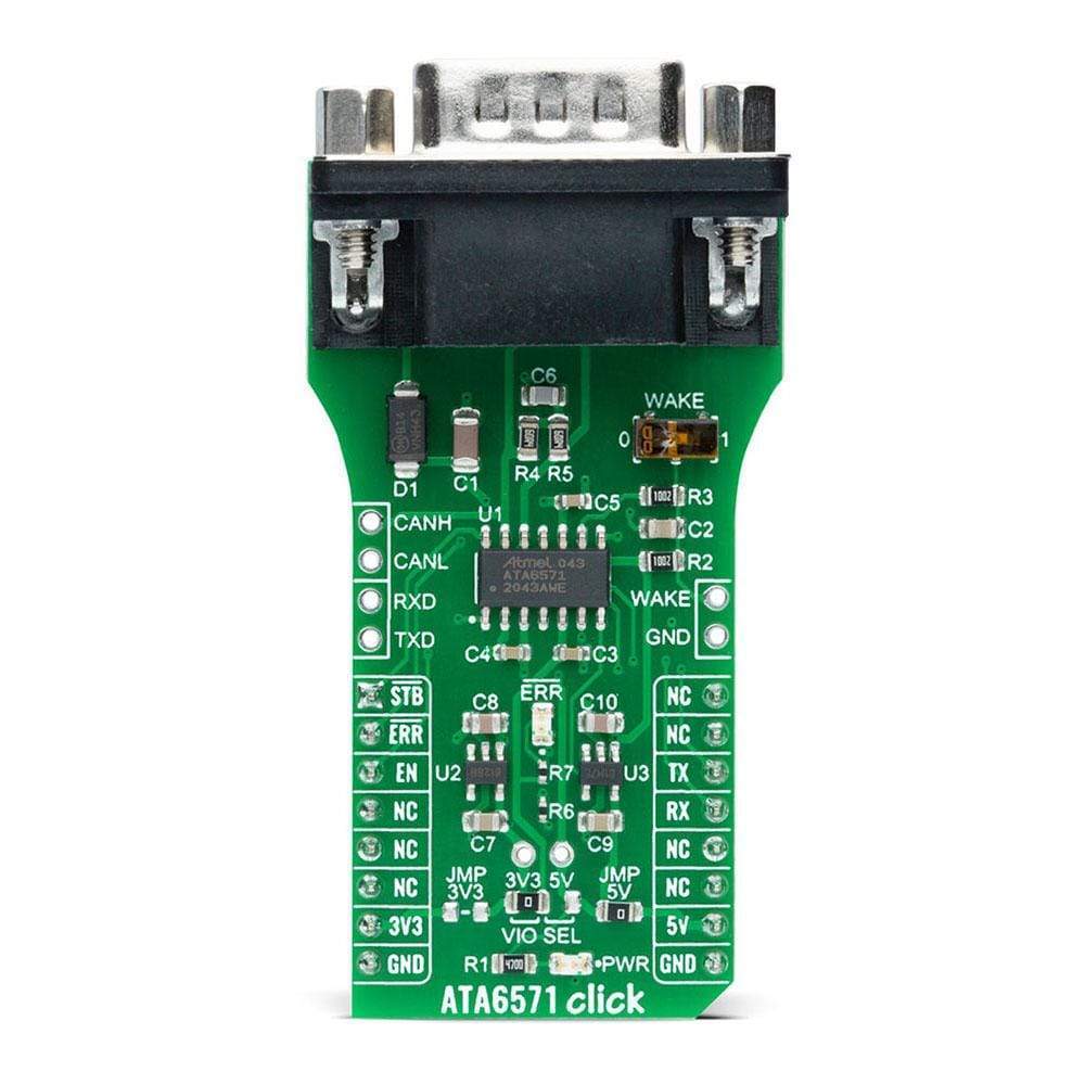
The ATA6571 Click Board™ is a compact add-on board containing a transceiver for high-speed CAN applications. This board features the ATA6571, a standalone high-speed CAN FD transceiver that interfaces a CAN protocol controller and the physical two-wire CAN bus from Microchip. It offers several operating modes with diagnostic and fail-safe features that enhance system reliability. Its advanced low-power management with local and remote Wake-Up support makes it possible to achieve low current consumption in Standby and Sleep mode. This Click Board™ is suitable for all types of high-speed CAN networks, especially in nodes requiring low-power mode with wake-up capability via the CAN bus.
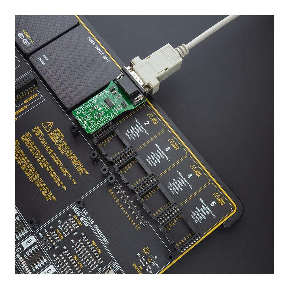
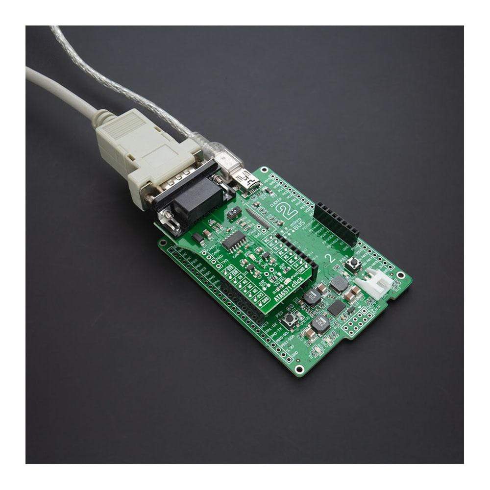
The ATA6571 Click Board™ is supported by a mikroSDK compliant library, which includes functions that simplify software development. This Click Board™ comes as a thoroughly tested product, ready to be used on a system equipped with the mikroBUS™ socket.
Downloads
L' ATA6571 Click Board™ est une carte complémentaire compacte contenant un émetteur-récepteur pour les applications CAN à haut débit. Cette carte comprend l'ATA6571, un émetteur-récepteur CAN FD à haut débit autonome qui interface un contrôleur de protocole CAN et le bus CAN physique à deux fils de Microchip. Il offre plusieurs modes de fonctionnement avec des fonctions de diagnostic et de sécurité qui améliorent la fiabilité du système. Sa gestion avancée de faible consommation avec prise en charge du réveil local et à distance permet d'obtenir une faible consommation de courant en mode veille et veille prolongée. Cette Click Board™ convient à tous les types de réseaux CAN à haut débit, en particulier dans les nœuds nécessitant un mode basse consommation avec capacité de réveil via le bus CAN.
La carte Click Board™ ATA6571 est prise en charge par une bibliothèque compatible mikroSDK, qui comprend des fonctions qui simplifient le développement logiciel. Cette carte Click Board™ est un produit entièrement testé, prêt à être utilisé sur un système équipé du socket mikroBUS™.
| General Information | |
|---|---|
Part Number (SKU) |
MIKROE-4381
|
Manufacturer |
|
| Physical and Mechanical | |
Weight |
0.027 kg
|
| Other | |
EAN |
8606027381386
|
Frequently Asked Questions
Have a Question?
Be the first to ask a question about this.