


Mikroelektronika d.o.o.
Carte Brushless 12 Click
Carte Brushless 12 Click
SKU: MIKROE-4357
Impossible de charger la disponibilité du service de retrait


Overview
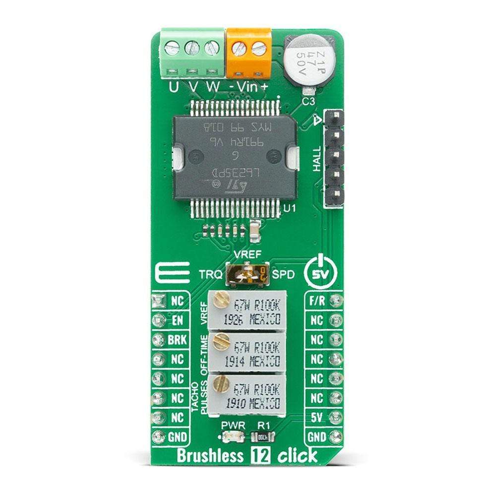
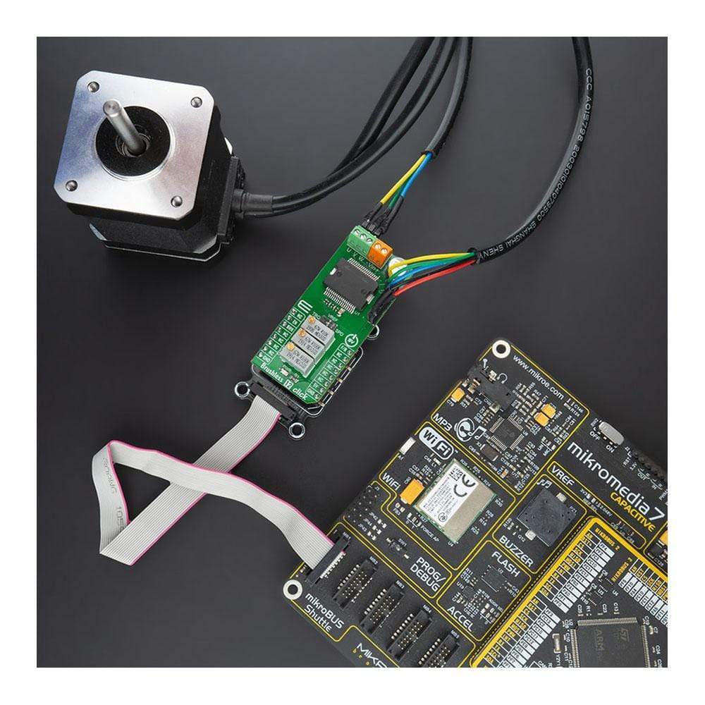
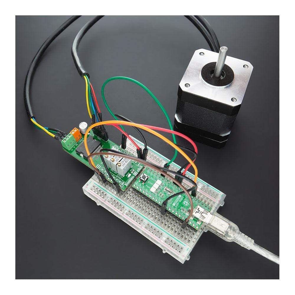
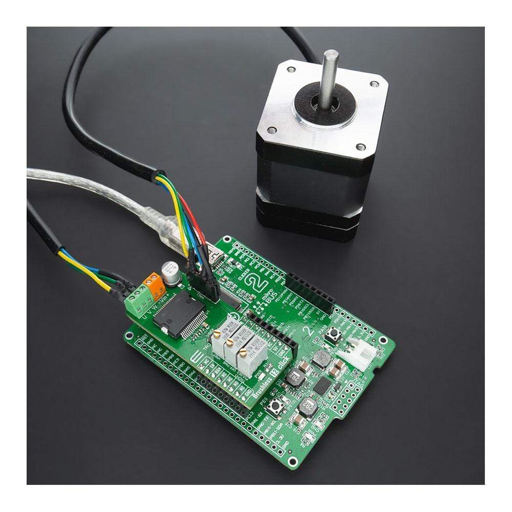
The Brushless 12 Click Board™ is a compact add-on board that controls BLDC motors with any MCU. This board features the L6235, DMOS fully integrated 3-phase motor driver with overcurrent protection from STMicroelectronics. The L6235 combines the chip's isolated DMOS power transistors with CMOS and bipolar circuits. It features a non-dissipative overcurrent protection on the high-side power MOSFETs and thermal shutdown and includes all the circuitry needed to drive a 3-phase brushless DC motor. This Click Board™ makes the perfect solution for small home appliances, robotics, battery-powered systems, small cooling fans, and many more.
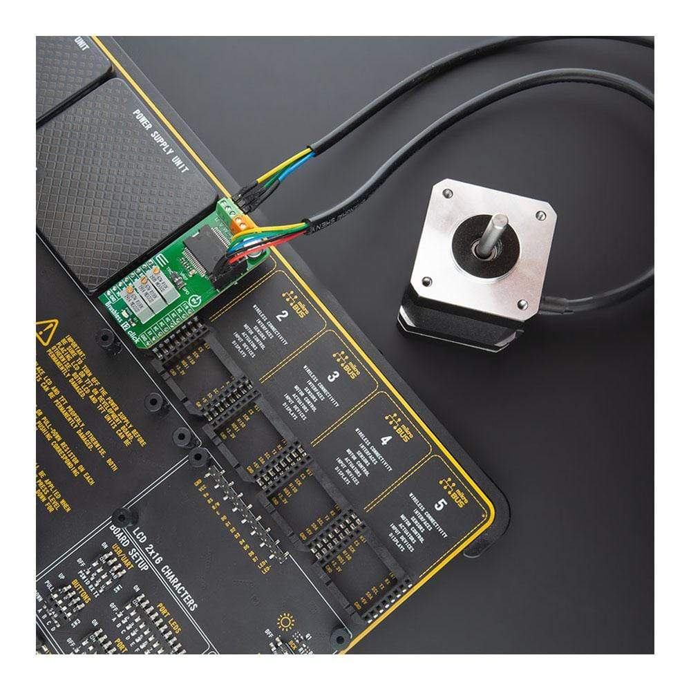
The Brushless 12 Click is supported by a mikroSDK-compliant library, which includes functions that simplify software development. This Click Board™ comes as a thoroughly tested product, ready to be used on a system equipped with the mikroBUS™ socket.
Downloads
La carte Brushless 12 Click Board™ est une carte complémentaire compacte qui contrôle les moteurs BLDC avec n'importe quel microcontrôleur. Cette carte est équipée du pilote de moteur triphasé entièrement intégré DMOS L6235 avec protection contre les surintensités de STMicroelectronics. Le L6235 combine les transistors de puissance DMOS isolés de la puce avec des circuits CMOS et bipolaires. Il est doté d'une protection contre les surintensités non dissipative sur les MOSFET de puissance côté haut et d'un arrêt thermique et comprend tous les circuits nécessaires pour piloter un moteur CC sans balais triphasé. Cette carte Click Board™ est la solution parfaite pour les petits appareils électroménagers, la robotique, les systèmes alimentés par batterie, les petits ventilateurs de refroidissement et bien d'autres encore.
Le Brushless 12 Click est pris en charge par une bibliothèque compatible mikroSDK, qui comprend des fonctions qui simplifient le développement logiciel. Ce Click Board™ est un produit entièrement testé, prêt à être utilisé sur un système équipé du socket mikroBUS™.
| General Information | |
|---|---|
Part Number (SKU) |
MIKROE-4357
|
Manufacturer |
|
| Physical and Mechanical | |
Weight |
0.027 kg
|
| Other | |
EAN |
8606027381225
|
Frequently Asked Questions
Have a Question?
Be the first to ask a question about this.