


Mikroelektronika d.o.o.
Tableau de clic CXPI
Tableau de clic CXPI
SKU: MIKROE-4336
Impossible de charger la disponibilité du service de retrait


Overview
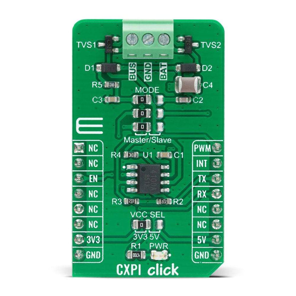
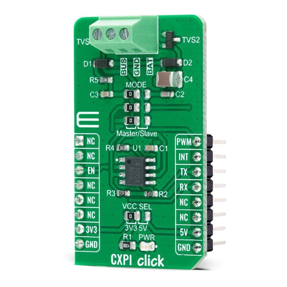
The CXPI Click Board™ is a compact add-on board that contains a transceiver that supports the next-generation automotive communication protocol. This board features the BD41000AFJ-C, a transceiver for the CXPI (Clock Extension Peripheral Interface) communication from Rohm Semiconductor. It operates from 7V to 18V external power supply, features easy switching between Master or Slave Mode, arbitration function that stops the data output upon detection of BUS data collision, and fail-safe functions that suspend the output data upon detection of under-voltage or temperature abnormality. This Click Board™ is suitable for use in body control applications, including steering switch, AC, and instrument panel systems.
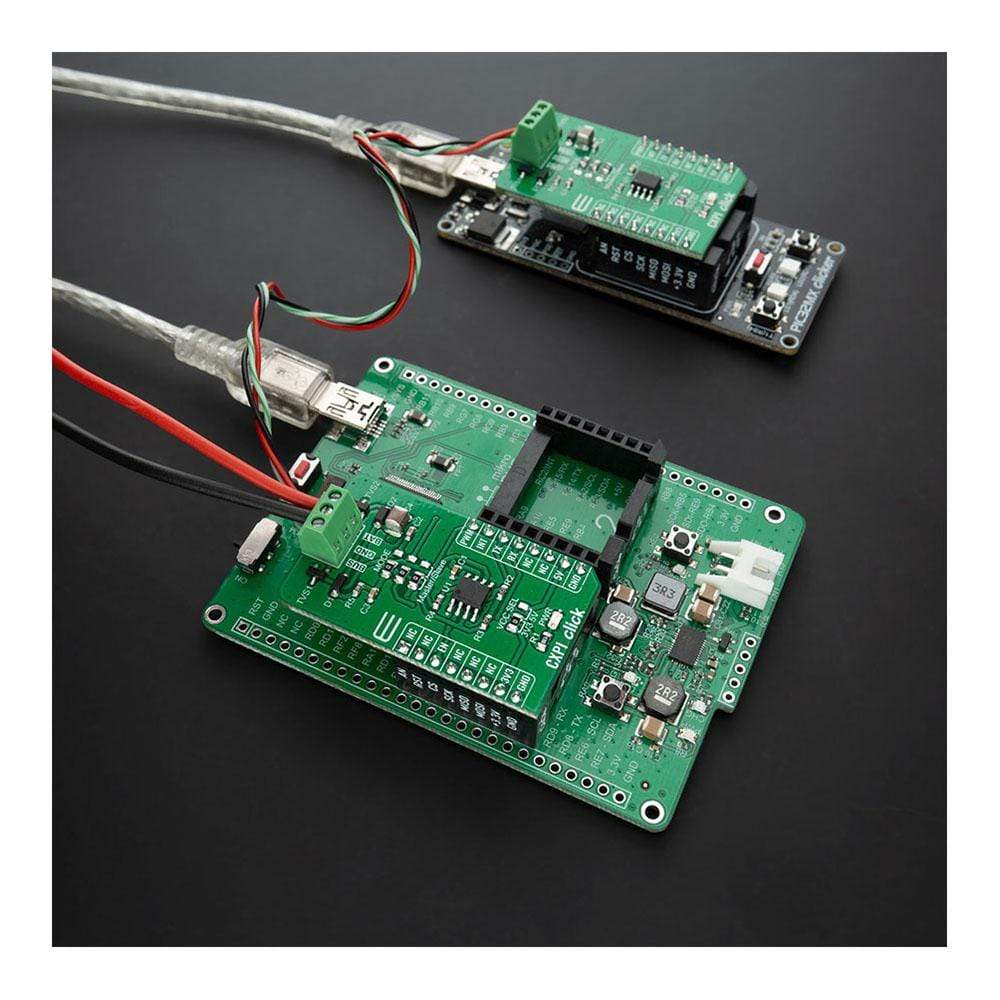
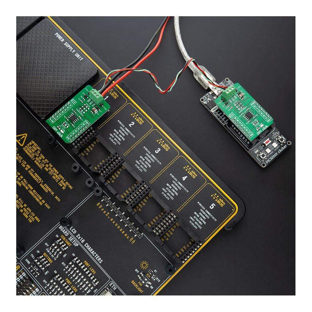
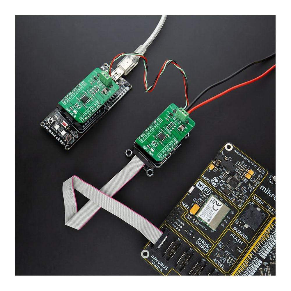
The CXPI Click Board™ is supported by a mikroSDK compliant library, which includes functions that simplify software development. This Click Board™ comes as a fully tested product, ready to be used on a system equipped with the mikroBUS™ socket.
Downloads
Le CXPI Click Board™ est une carte complémentaire compacte qui contient un émetteur-récepteur prenant en charge le protocole de communication automobile de nouvelle génération. Cette carte comprend le BD41000AFJ-C, un émetteur-récepteur pour la communication CXPI (Clock Extension Peripheral Interface) de Rohm Semiconductor. Il fonctionne à partir d'une alimentation externe de 7 V à 18 V, offre une commutation facile entre le mode maître ou esclave, une fonction d'arbitrage qui arrête la sortie de données lors de la détection d'une collision de données BUS et des fonctions de sécurité intégrée qui suspendent les données de sortie lors de la détection d'une sous-tension ou d'une anomalie de température. Ce Click Board™ convient à une utilisation dans les applications de contrôle de carrosserie, notamment les systèmes de commutateur de direction, de climatisation et de tableau de bord.
La carte Click Board™ CXPI est prise en charge par une bibliothèque compatible mikroSDK, qui comprend des fonctions qui simplifient le développement logiciel. Cette carte Click Board™ est un produit entièrement testé, prêt à être utilisé sur un système équipé du socket mikroBUS™.
| General Information | |
|---|---|
Part Number (SKU) |
MIKROE-4336
|
Manufacturer |
|
| Physical and Mechanical | |
Weight |
0.019 kg
|
| Other | |
EAN |
8606027381034
|
Frequently Asked Questions
Have a Question?
Be the first to ask a question about this.