


Mikroelektronika d.o.o.
Carte à clic CAN FD 5
Carte à clic CAN FD 5
SKU: MIKROE-4286
Impossible de charger la disponibilité du service de retrait
Overview
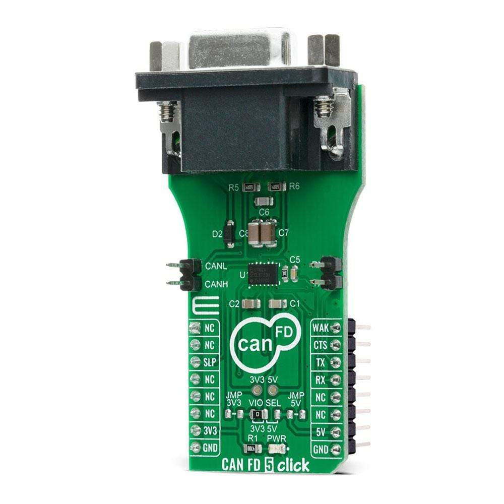
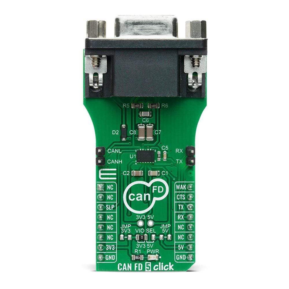
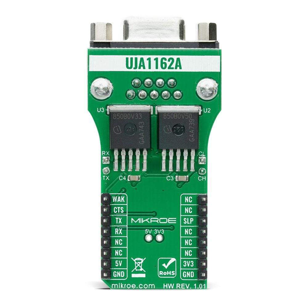
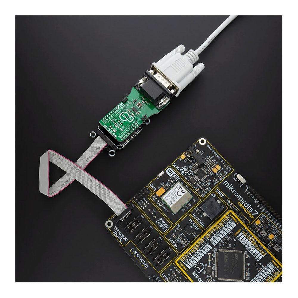
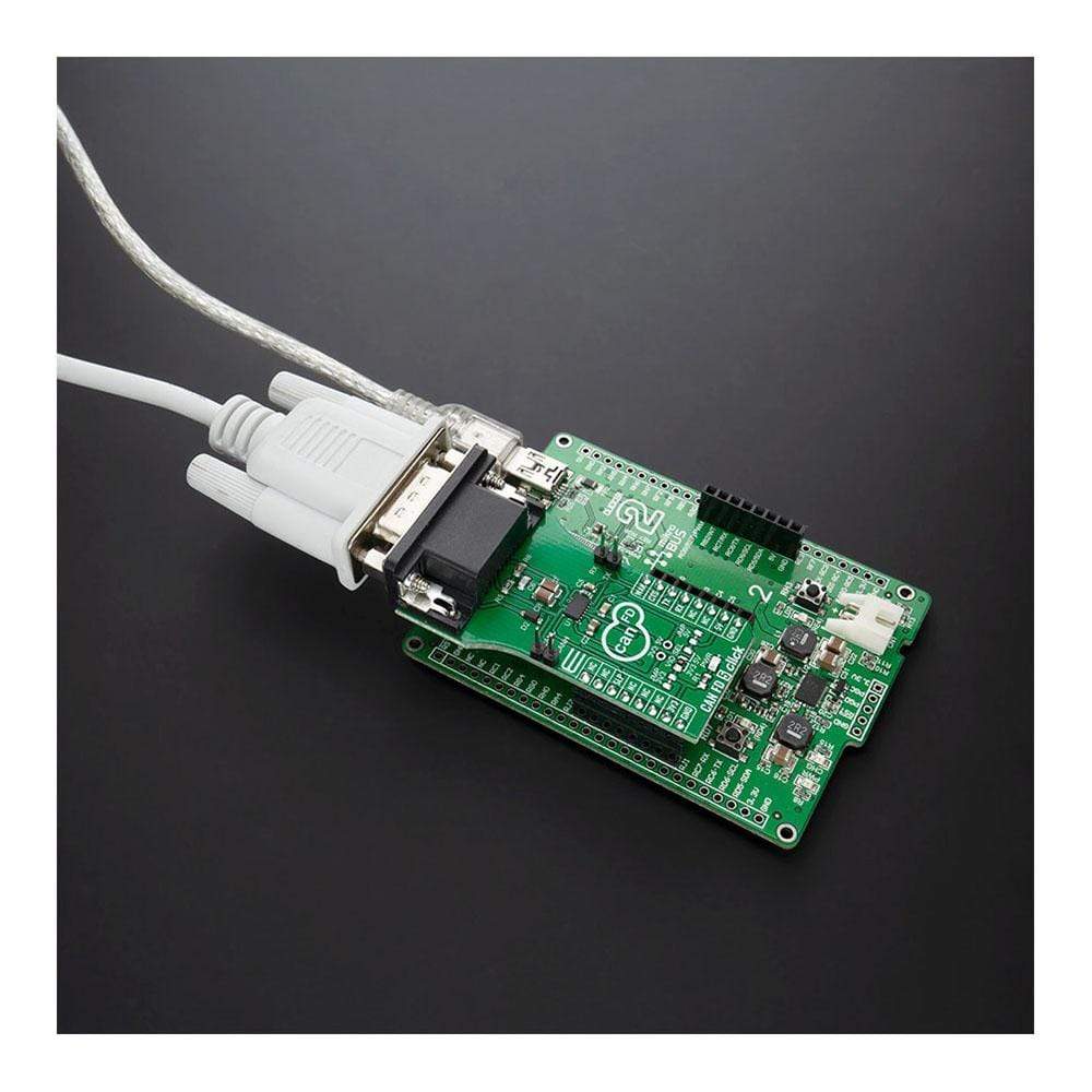
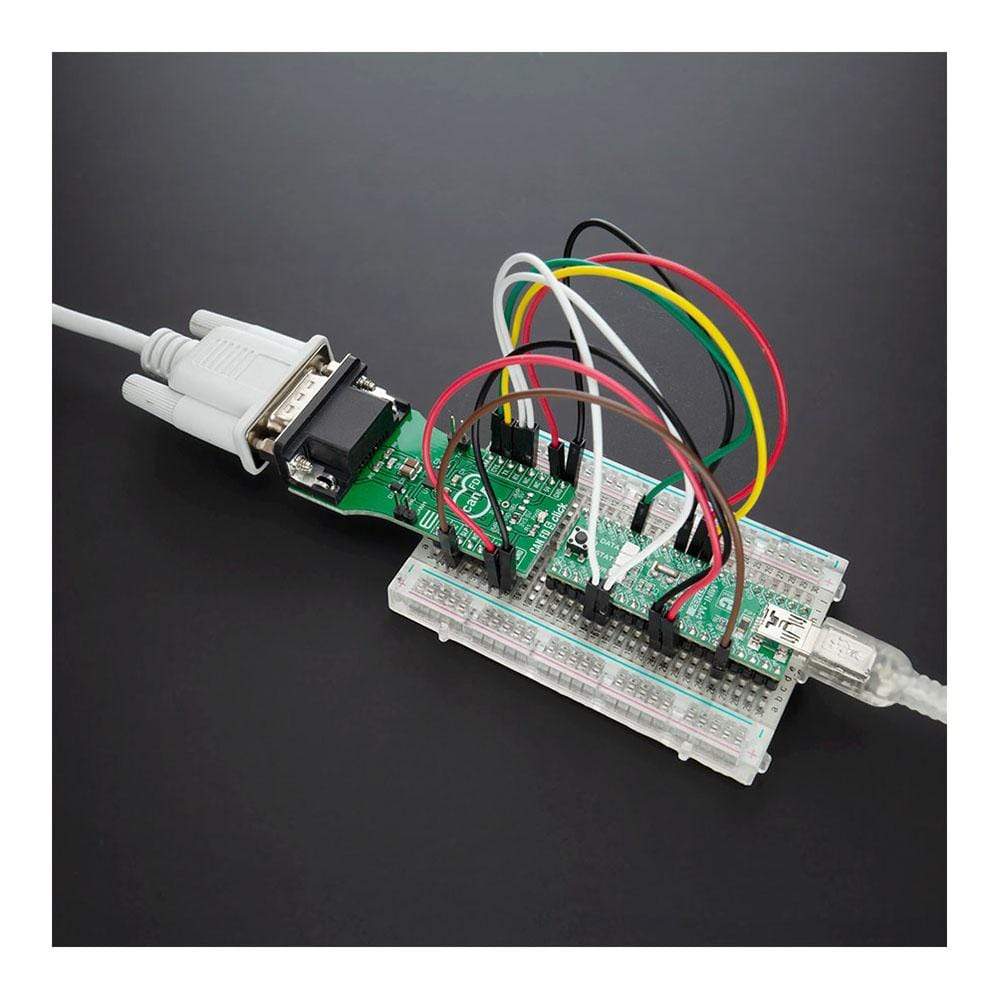
The CAN FD 5 Click Board™ is a compact add-on board that contains a high-speed CAN transceiver that supports both CAN and CAN FD protocol types. This board features the UJA1162A, a ‘self-supplied high-speed CAN transceiver integrating an ISO 11898-2:2016 and SAE J2284-1 to SAE J2284-5 compliant CAN transceiver with Sleep Mode from NXP Semiconductors. It supports many additional features like under-voltage detection, mode control via a single GPIO pin, remote and local wake-up capability, overtemperature shutdown, and a very low quiescent current in Sleep mode. This Click Board™ is suitable for HS CAN networks in automotive applications and networks in industrial applications, in electric power steering (EPS), HVAC climate control, tire pressure monitoring system (TPMS), and many more.
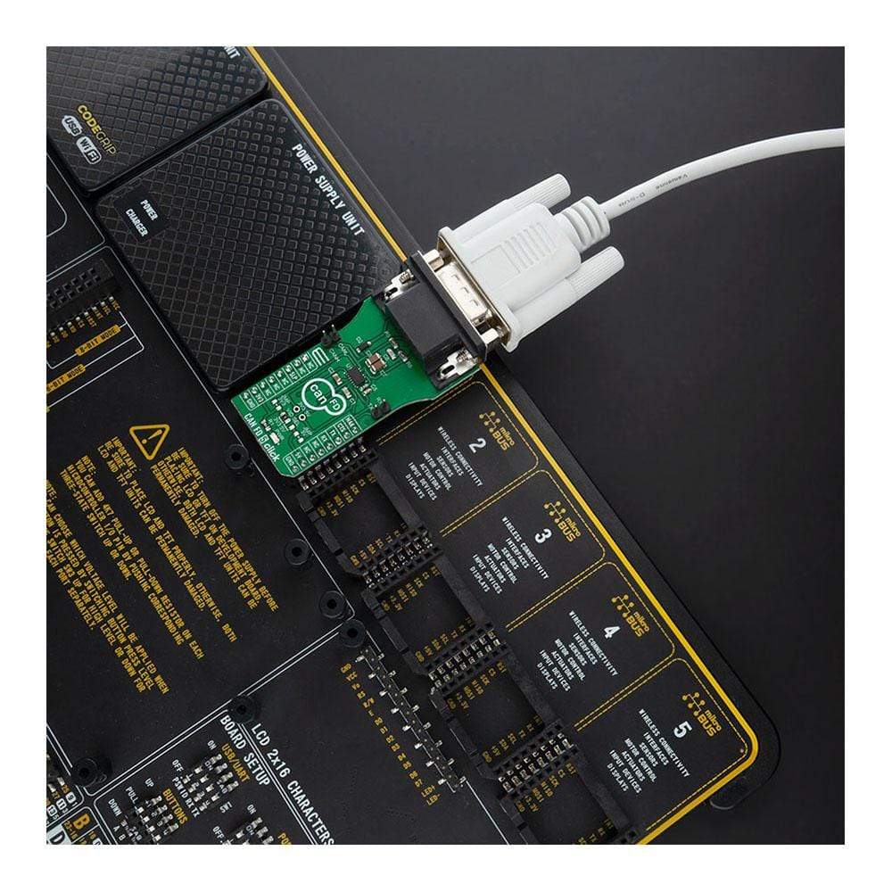
The CAN FD 5 Click Board™ is supported by a mikroSDK compliant library, which includes functions that simplify software development. This Click Board™ comes as a fully tested product, ready to be used on a system equipped with the mikroBUS™ socket.
Downloads
La carte Click Board™ CAN FD 5 est une carte complémentaire compacte qui contient un émetteur-récepteur CAN haute vitesse qui prend en charge les types de protocole CAN et CAN FD. Cette carte comprend l'UJA1162A, un émetteur-récepteur CAN haute vitesse auto-alimenté intégrant un émetteur-récepteur CAN conforme aux normes ISO 11898-2:2016 et SAE J2284-1 à SAE J2284-5 avec mode veille de NXP Semiconductors. Il prend en charge de nombreuses fonctionnalités supplémentaires telles que la détection de sous-tension, le contrôle de mode via une seule broche GPIO, la capacité de réveil à distance et locale, l'arrêt en cas de surchauffe et un courant de repos très faible en mode veille. Cette carte Click Board™ convient aux réseaux CAN HS dans les applications automobiles et aux réseaux dans les applications industrielles, dans la direction assistée électrique (EPS), la climatisation CVC, le système de surveillance de la pression des pneus (TPMS) et bien d'autres.
La carte Click Board™ CAN FD 5 est prise en charge par une bibliothèque compatible mikroSDK, qui comprend des fonctions qui simplifient le développement logiciel. Cette carte Click Board™ est un produit entièrement testé, prêt à être utilisé sur un système équipé de la prise mikroBUS™.
| General Information | |
|---|---|
Part Number (SKU) |
MIKROE-4286
|
Manufacturer |
|
| Physical and Mechanical | |
Weight |
0.033 kg
|
| Other | |
EAN |
8606027380648
|
Frequently Asked Questions
Have a Question?
Be the first to ask a question about this.