Carte à clic WiFi 11
Overview
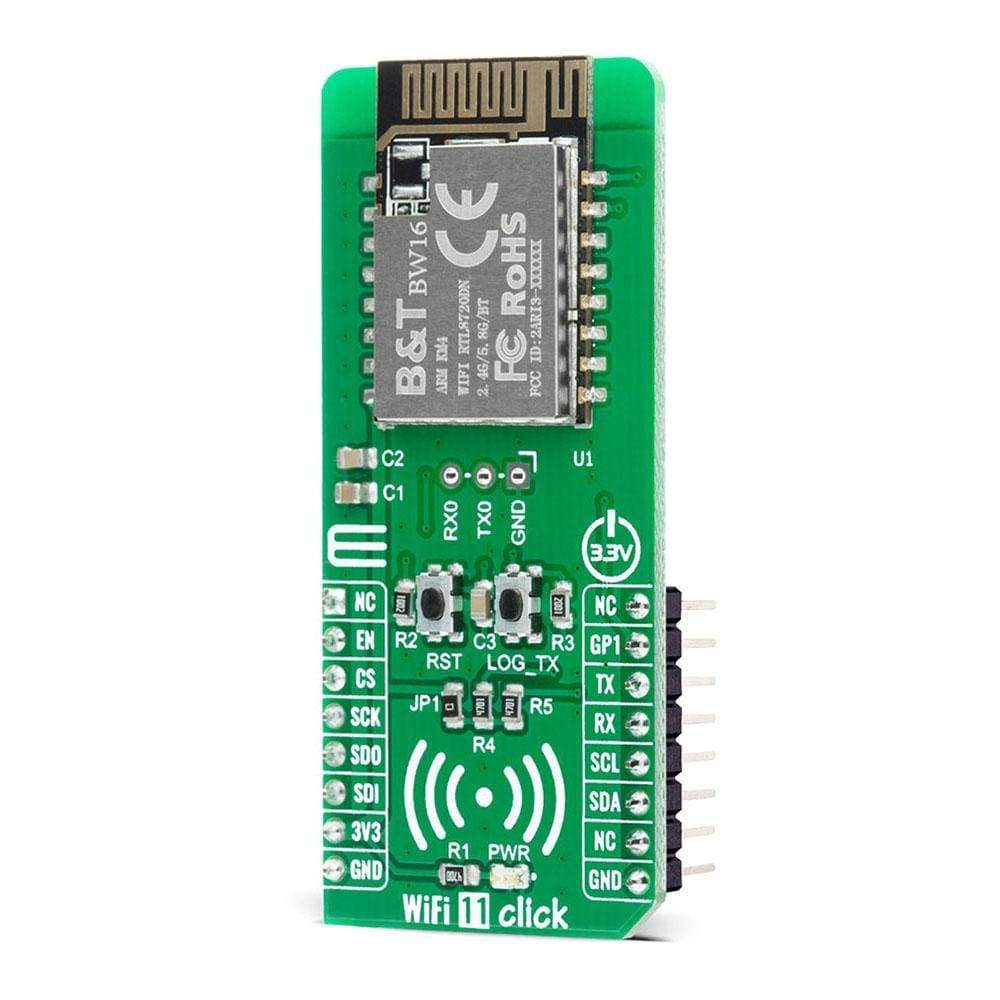
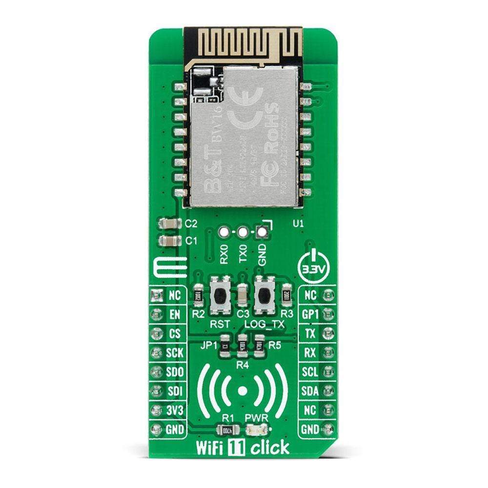
Le WiFi 11 Click Board™ est une carte complémentaire compacte qui contient un module WiFi et Bluetooth doté de deux bandes pour la communication WiFi. Cette carte comprend le BW16, un module SoC Bluetooth Low Energy et LAN sans fil (WLAN) à double bande à faible consommation de Shenzhen B&T Technologies Co., Ltd. Ce module prend en charge le WiFi 5G et le Bluetooth Low Energy 5.0, il se compose d'un MCU hautes performances sur un module nommé KM4, d'un MCU basse consommation nommé KM0, d'un MAC WLAN (802.11 a/b/g/n), d'une bande de base WLAN compatible 1T1R, RF, Bluetooth et de périphériques. Une antenne interne et de nombreuses interfaces sont disponibles dans ce module WiFi et Bluetooth. Ce Click Board™ convient au contrôle sans fil industriel, à la passerelle Bluetooth, aux étiquettes d'identification de sécurité, aux applications de maison intelligente et bien d'autres.
Le Click WiFi 11 est pris en charge par une bibliothèque compatible mikroSDK, qui comprend des fonctions qui simplifient le développement logiciel. Ce Click Board™ est un produit entièrement testé, prêt à être utilisé sur un système équipé de la prise mikroBUS™.
How Does The WiFi 11 Click Board™ Work?
The WiFi 11 Click Board™ is based on the BW16, a low-power dual bands Wireless LAN (WLAN) and Bluetooth Low Energy SoC module from Ai-Thinker. The BW16 module represents a highly integrated Wi-Fi and Bluetooth SOC based on the RTL8720DN, a highly integrated Single-Chip with a low power dual bands (2.4GHz and 5GHz), Wireless LAN (WLAN), and Bluetooth Low Energy (v5.0). It consists of a high-performance MCU (ARM V8M, Cortex-M4F instruction compatible) named KM4, a low power MCU (ARM V8M, Cortex-M0 instruction compatible) named KM0, WLAN (802.11 a/b/g/n) MAC, a 1T1R capable WLAN baseband, RF, Bluetooth, and other peripherals. The BW16 integrates internal memories for complete WIFI and BLE 5.0 protocol functions. The embedded memory configuration also provides simple application developments.
The WiFi 11 Click Board™ communicates with MCU using the UART interface at 57600 bps as its default communication protocol, but it is also left the option for the user to use other interfaces such as SPI and I2C if he wants to configure the module and write the library by himself. There is also a jumper JP1 on this Click board™ that enables the necessary pull-up resistors on the SCL and SDA lines of I2C communication.
NOTE: After primary module initialization, and before any program uploading, user should write network parameters and TCP server parameters.
Additional functionality such as the Chip Enable button labelled as RST, which is used to Enable or put the module in Shut-Down mode, is provided and routed at EN pin of the mikroBUS™ socket. Alongside this pin, this Click board™ has one general purpose pin GP1 routed at the INT pin of the mikroBUS™ socket, which can be used in various cases like interrupt or some other purposes. WiFi 11 Click also has an additional header with UART RX0 and TX0 module pins on itself together with a button labelled as LOG_TX which can be used for Firmware Update or as low-power mode Wake-Up function.
The WiFi 11 Click Board™ is designed to be operated only with a 3.3V logic voltage level. A proper logic voltage level conversion should be performed before the Click board™ is used with MCUs with different logic levels. However, the Click board™ comes equipped with a library that contains easy to use functions and a usage example that may be used as a reference for further development.
SPECIFICATIONS
Type | WiFi |
Applications | Can be used for industrial wireless control, Bluetooth gateway, security ID tags, smart home applications, and many more. |
On-board modules | The WiFi 11 Click Board™ is based on the BW16, a low-power dual bands Wireless LAN (WLAN) and Bluetooth Low Energy SoC module from Ai-Thinker. |
Key Features | Ultra-low power consumption, support low-power Tx/Rx for short-range applications, support BLE, supported TrustZone-M and Secure boot, eFuse protection, and more. |
Interface | I2C,SPI,UART |
Compatibility | mikroBUS |
Click board size | L (57.15 x 25.4 mm) |
Input Voltage | 3.3V |
PINOUT DIAGRAM
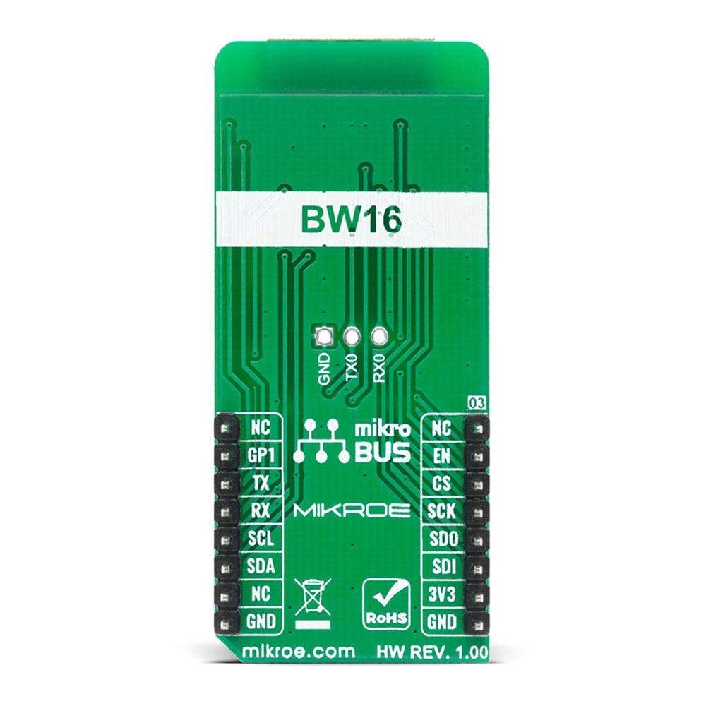
This table shows how the pinout of the WiFi 11 Click Board™ corresponds to the pinout on the mikroBUS™ socket (the latter shown in the two middle columns).
Notes | Pin | Pin | Notes | ||||
---|---|---|---|---|---|---|---|
NC | 1 | AN | PWM | 16 | NC | ||
Chip Enable | EN | 2 | RST | INT | 15 | GP1 | General Purpose Pin |
SPI Chip Select | CS | 3 | CS | RX | 14 | TX | UART TX |
SPI Clock | SCK | 4 | SCK | TX | 13 | RX | UART RX |
SPI Data OUT | SDO | 5 | MISO | SCL | 12 | SCL | I2C Clock |
SPI Data IN | SDI | 6 | MOSI | SDA | 11 | SDA | I2C Data |
Power Supply | 3.3V | 7 | 3.3V | 5V | 10 | NC | |
Ground | GND | 8 | GND | GND | 9 | GND | Ground |
ONBOARD SETTINGS AND INDICATORS
Label | Name | Default | Description |
---|---|---|---|
LD1 | PWR | - | Power LED Indicator |
JP1 | - | - | I2C Pull-Up Resistor Selector |
J1 | M1X3 | - | UART FW Update Header |
T1 | LOG_TX | - | FW Update Button |
T2 | RST | - | Chip Enable Button |
WIFI 11 CLICK ELECTRICAL SPECIFICATIONS
Description | Min | Typ | Max | Unit |
---|---|---|---|---|
Supply Voltage | - | 3.3 | - | V |
Frequency Range | 2.412 / 5.180 | - | 2.484 / 5.825 | GHz |
Receiver Sensitivity | - | -92 | - | dBm |
Transmit Power | - | 7±2 | - | dBm |
Operating Temperature Range | -20 | - | +85 | °C |
Software Support
We provide a library for the WiFi 11 Click Board™ on our LibStock page, as well as a demo application (example), developed using MikroElektronika compilers. The demo can run on all the main MikroElektronika development boards.
Library Description
The library contains a basic functions for using the WiFi 11 Click Board™.
Key Functions
void wifi11_set_conect_to_ap( char *username, char *password )
- Connect to APvoid wifi11_send_command ( uint8_t *cmd )
- Send command
Example Description
The application is composed of three sections :
- System Initialization - Initializes UART module and all necessary GPIO pins
- Application Initialization - Initializes driver module and starts sending AT commands.
- Example : TCP client - Please, before the uploaded program you should write network parameters and TCP server parameters.
void application_init ( ) { wifi11_uart_driver_init ( ( wifi11_obj_t )&_MIKROBUS1_GPIO, ( wifi11_obj_t )&_MIKROBUS1_UART ); Delay_ms( 200 ); wifi11_reset_device( ); Delay_ms( 5000 ); mikrobus_logWrite( "---- Start test command -----", _LOG_LINE ); wifi11_send_command( &WIFI11_CMD_AT[ 0 ] ); Delay_ms( 200 ); wifi11_send_command( &WIFI11_CMD_ATSV[ 0 ] ); Delay_ms( 200 ); mikrobus_logWrite( "---- WiFi configuration -----", _LOG_LINE ); wifi11_send_command( &WIFI11_CMD_ATPW[ 0 ] ); Delay_ms( 1000 ); wifi11_set_conect_to_ap( &wifi11_net_username[ 0 ], &wifi11_net_password[ 0 ] ); Delay_ms( 10000 ); wifi11_send_command( &WIFI11_CMD_ATW[ 0 ] ); Delay_ms( 1000 ); mikrobus_logWrite( "---- TCP example (Client) -----", _LOG_LINE ); wifi11_send_command( &WIFI11_CMD_ATPC[ 0 ] ); Delay_ms( 10000 ); wifi11_send_command( &WIFI11_CMD_ATPT[ 0 ] ); Delay_ms( 1000 ); wifi11_send_command( &WIFI11_CMD_ATPK[ 0 ] ); Delay_ms( 1000 ); }
The full application code, and ready to use projects can be found on our LibStock page.
Other mikroE Libraries used in the example:
- UART Library
Additional Notes and Information
Depending on the development board you are using, you may need USB UART Click Board™, USB UART 2 Click Board™ or RS232 Click Board™ to connect to your PC, for development systems with no UART to USB interface available on the board. The terminal available in all MikroElektronika compilers, or any other terminal application of your choice, can be used to read the message.
MIKROSDK
The WiFi 11 Click Board™ is supported with mikroSDK - MikroElektronika Software Development Kit. To ensure proper operation of mikroSDK compliant Click board™ demo applications, mikroSDK should be downloaded from the LibStock and installed for the compiler you are using.
Frequently Asked Questions
Have a Question?
Be the first to ask a question about this.