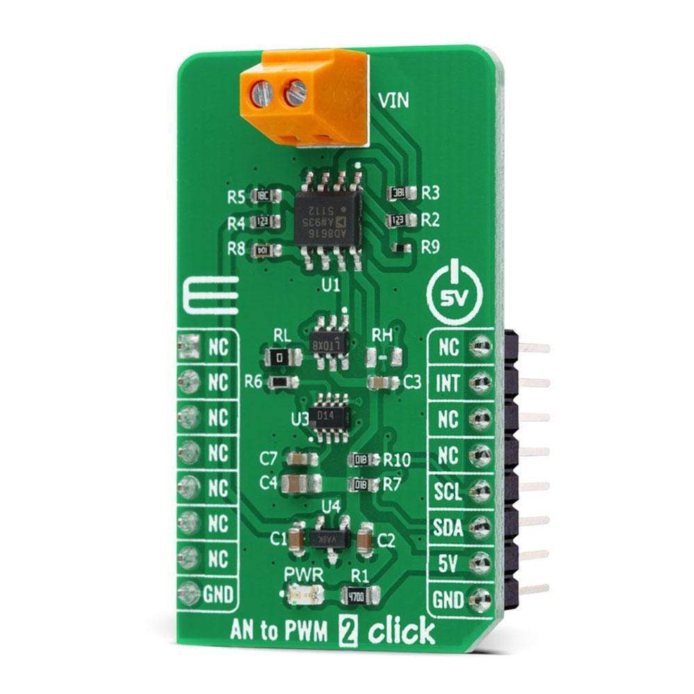
Carte à clic AN vers PWM 2
Overview
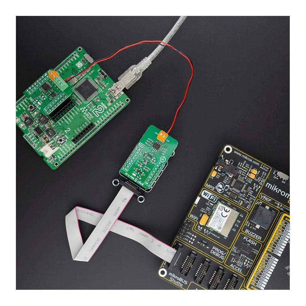
Le Carte Click Board™ AN vers PWM 2 est une carte complémentaire compacte qui contient un composant facile à utiliser qui convertit la valeur du signal analogique d'entrée en une sortie de tension PWM à fréquence fixe, avec un cycle de service proportionnel à la tension d'entrée. Cette carte comprend le LTC6992CS6, un oscillateur au silicium avec une capacité de modulation de largeur d'impulsion (PWM) contrôlée par tension analogique facile à utiliser d'Analog Devices. Il dispose du signal PWM contrôlé par une entrée analogique dans la plage de -2,5 V à 2,5 V, une plage de fréquence jusqu'à 1 MHz, une erreur de fréquence inférieure à 1,7 % et une bonne stabilité de température. Il possède de nombreuses fonctionnalités qui le rendent bien adapté au contrôle du chauffage, aux boucles d'asservissement PWM, à la gradation des LED, à l'isolation du signal et à d'autres applications de contrôle du cycle de service.
La carte Click Board™ AN to PWM 2 est prise en charge par une bibliothèque compatible mikroSDK, qui comprend des fonctions qui simplifient le développement logiciel. Cette carte Click Board™ est un produit entièrement testé, prêt à être utilisé sur un système équipé du socket mikroBUS™.
How Does The AN to PWM 2 Click Board Work?
The AN to PWM 2 Click Board™ is based on the LTC6992CS6, a voltage-controlled PWM generator from Analog Devices. This device is chosen because it keeps its output clocking at all times, and it offers glitch-free, a first cycle-accurate startup within 500μs of Power-On. The output of the this Click board™ can source or sink up to 16 mA, and it has a linear response, so applying a voltage in a range of -2.5 to 2.5V on its input, will result in generating the PWM pulse train with duty cycle linearly proportional to the input voltage. The output PWM signal is brought to the INT pin of the mikroBUS™ socket to enable fast and precise duty cycle measurement using the interrupt routines.
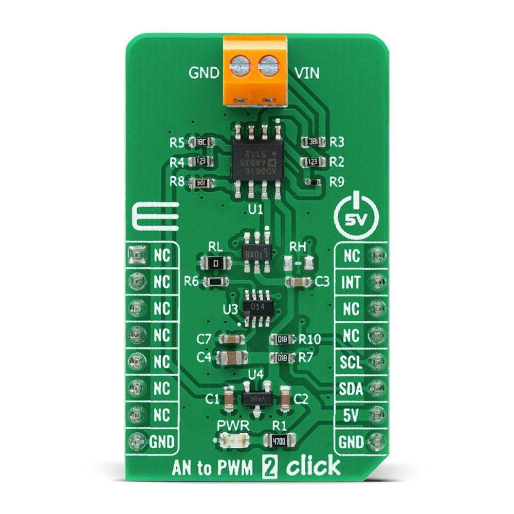
The LTC6992CS6 has a MOD pin which represents pulse-width modulation input where is necessary to bring an analog signal. To bring the corresponding signal to that pin, this Click board™ uses an analog circuitry made of OpAmp AD8616ARZ from Analog Devices. In the first part of the circuit, amplifier OPA1 attends to adjust the input signal through a reference voltage of 2.5V by the MCP1525 from Microchip and applied input voltage in a range of -2.5 to 2.5V. The next part of the circuit is the voltage divider and amplifier OPA2 which has the function of a buffer, after which the signal required by the MOD pin of the LTC6992CS6 is obtained.
The output frequency can range up from 3.81Hz to 1MHz and is controlled via the AD5171, a 64-position (OTP) digital potentiometer from Analog Devices, which programs the LTC6992CS6's internal master oscillator frequency. The output frequency is determined by this master oscillator and an internal frequency divider programmable to eight settings from 1 to 16384. It communicates with MCU using the standard I2C serial interface that operates at clock rates up to 400 kHz and represents the most accurate way to set the frequency. It's also left the possibility to adjust the frequency via resistors RH and RL by placing resistors of appropriate resistance.
The AN to PWM 2 Click Board™ is designed to be operated only with a 5V logic level. A proper logic voltage level conversion should be performed before the AN to PWM 2 Click is used with MCUs with different logic levels. More information about the LTC6992CS6's functionality, electrical specifications, and typical performance can be found in the attached datasheet. However, the Click board™ comes equipped with a library that contains easy-to-use functions, and a usage example that can be used as a reference for the development.
SPECIFICATIONS
Type | ADC |
Applications | Can be used for heater control, PWM servo loops, LED dimming, signal isolation, and other duty cycle control applications. |
On-board modules | AN to PWM 2 Click is based on the LTC6992CS6, a voltage-controlled PWM generator from Analog Devices. |
Key Features | Low power consumption, good temperature stability, wide frequency range, low frequency error, and more. |
Interface | I2C |
Compatibility | mikroBUS |
Click board size | M (42.9 x 25.4 mm) |
Input Voltage | 5V |
PINOUT DIAGRAM
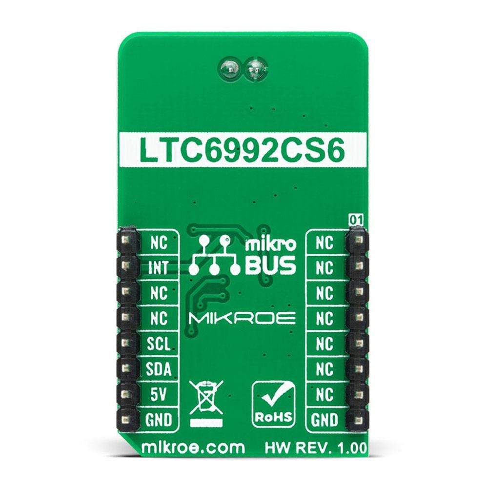
This table shows how the pinout on the AN to PWM 2 Click Board™ corresponds to the pinout on the mikroBUS™ socket (the latter shown in the two middle columns).
Notes | Pin | Pin | Notes | ||||
---|---|---|---|---|---|---|---|
NC | 1 | AN | PWM | 16 | NC | ||
NC | 2 | RST | INT | 15 | INT | PWM OutPut | |
NC | 3 | CS | RX | 14 | NC | ||
NC | 4 | SCK | TX | 13 | NC | ||
NC | 5 | MISO | SCL | 12 | SCL | I2C Clock | |
NC | 6 | MOSI | SDA | 11 | SDA | I2C Data | |
NC | 7 | 3.3V | 5V | 10 | 5V | Power Supply | |
Ground | GND | 8 | GND | GND | 9 | GND | Ground |
ONBOARD SETTINGS AND INDICATORS
Label | Name | Default | Description |
---|---|---|---|
LD1 | PWR | - | Power LED Indicator |
AN to PWM 2 CLICK ELECTRICAL SPECIFICATIONS
Description | Min | Typ | Max | Unit |
---|---|---|---|---|
Input Supply Voltage | -2.5 | - | +2.5 | V |
Output Current | - | ±20 | - | mA |
Output Frequency | 3.81 Hz | - | 10 | MHz |
Operating Temperature Range | -40 | - | +85 | °C |
Software Support
We provide a library for the AN to PWM 2 Click Board™ on our LibStock page, as well as a demo application (example), developed using MikroElektronika compilers. The demo can run on all the main MikroElektronika development boards.
Library Description
The library contains basic function for sets frequency and gets interrupt pin state.
Key Functions
uint8_t antopwm2_get_int_state ( void )
- Gets interrupt pin statevoid antopwm2_set_freq ( uint8_t freq )
- Set Frequency
Example Description
The application is composed of three sections :
- System Initialization - Initializes the INT pin required to measure.
- Application Initialization - Initializes the driver, timer on 1us and frequency
void application_task ( ) { uint8_t drdy; char rsp_data; drdy = UART_Rdy_Ptr( ); if ( drdy != 0 ) { rsp_data = UART_Rd_Ptr( ); switch ( rsp_data ) { case '+' : { // Reset flags period_flag = 0; idle_high_cnt = 0; idle_low_cnt = 0; period_cnt = 0; while ( period_flag != 1 ); idle_high_cnt /= 10; idle_low_cnt /= 10; if ( ( idle_high_cnt != 0 ) && ( idle_high_cnt != 0 ) ) { tmp_value = calc_percentage( idle_high_cnt ); FloatToStr( tmp_value, demo_text ); mikrobus_logWrite( "> Idle [HIGH]: ~ ", _LOG_TEXT ); mikrobus_logWrite( demo_text, _LOG_TEXT ); mikrobus_logWrite( " %", _LOG_LINE ); tmp_value = calc_percentage( idle_low_cnt ); FloatToStr( tmp_value, demo_text ); mikrobus_logWrite( "> Idle [LOW]: ~ ", _LOG_TEXT ); mikrobus_logWrite( demo_text, _LOG_TEXT ); mikrobus_logWrite( " %", _LOG_LINE ); tmp_value = calc_voltage( idle_high_cnt ); FloatToStr( tmp_value , demo_text ); mikrobus_logWrite( "> Voltage: ~ ", _LOG_TEXT ); mikrobus_logWrite( demo_text, _LOG_TEXT ); mikrobus_logWrite( " mV", _LOG_LINE ); mikrobus_logWrite( "--------------------------------", _LOG_LINE ); } mikrobus_logWrite( "--- Please, enter the command [ + ].", _LOG_LINE ); break; } } } }
Additional Functions :
- calc_percentage( ) - Represented data as a percentage
- calc_voltage( ) - Voltage calculation
- timer_init_1us( ) - Sets timer on 1us
The full application code, and ready to use projects can be found on our LibStock page.
Other mikroE Libraries used in the example:
- I2C Library
- Conversions Library
Additional Notes and Information
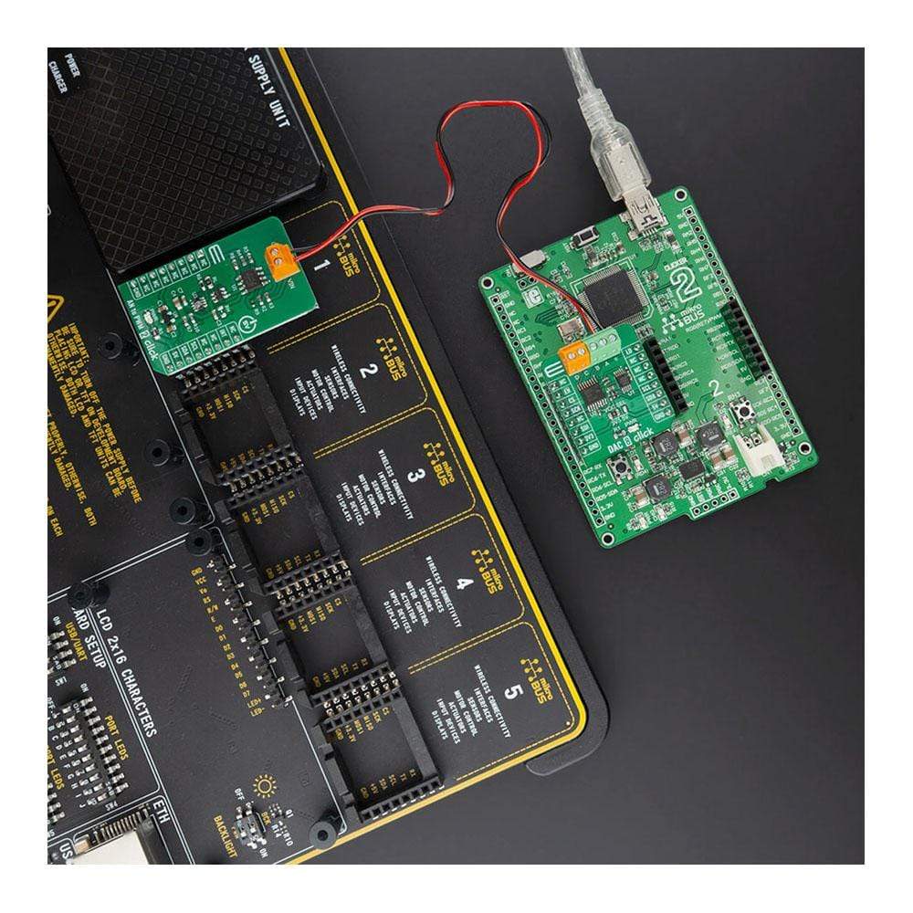
Depending on the development board you are using, you may need a USB UART click, USB UART 2 click or RS232 click to connect to your PC, for development systems with no UART to USB interface available on the board. The terminal available in all MikroElektronika compilers, or any other terminal application of your choice, can be used to read the message.
MIKROSDK
The AN to PWM 2 Click Board™ is supported with mikroSDK - MikroElektronika Software Development Kit. To ensure proper operation of mikroSDK compliant Click board™ demo applications, mikroSDK should be downloaded from the LibStock and installed for the compiler you are using.
Frequently Asked Questions
Have a Question?
Be the first to ask a question about this.