Carte de clic de température de surface
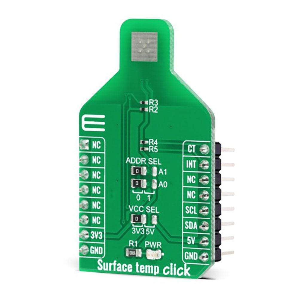
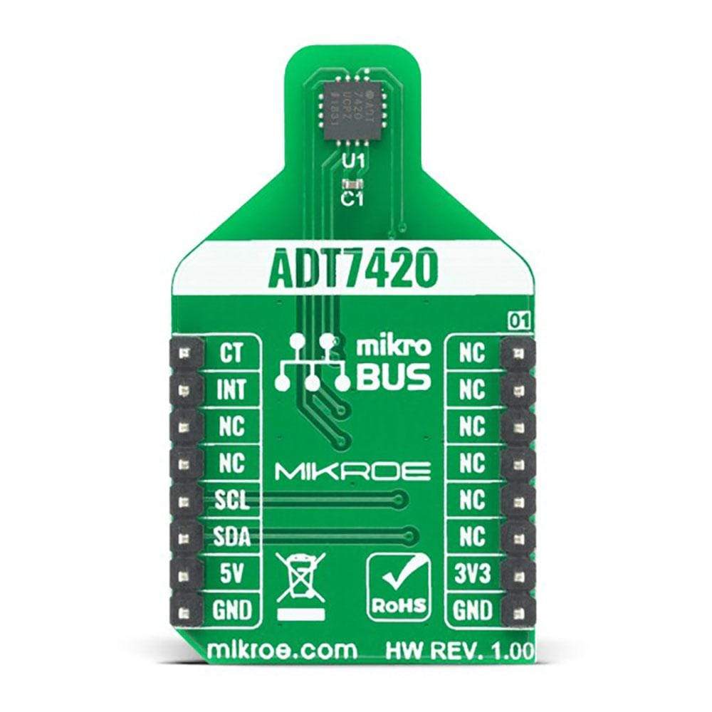
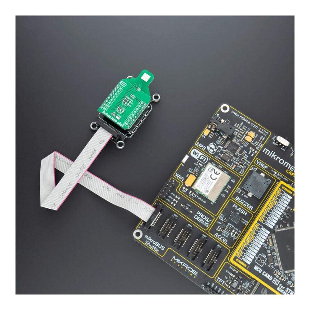
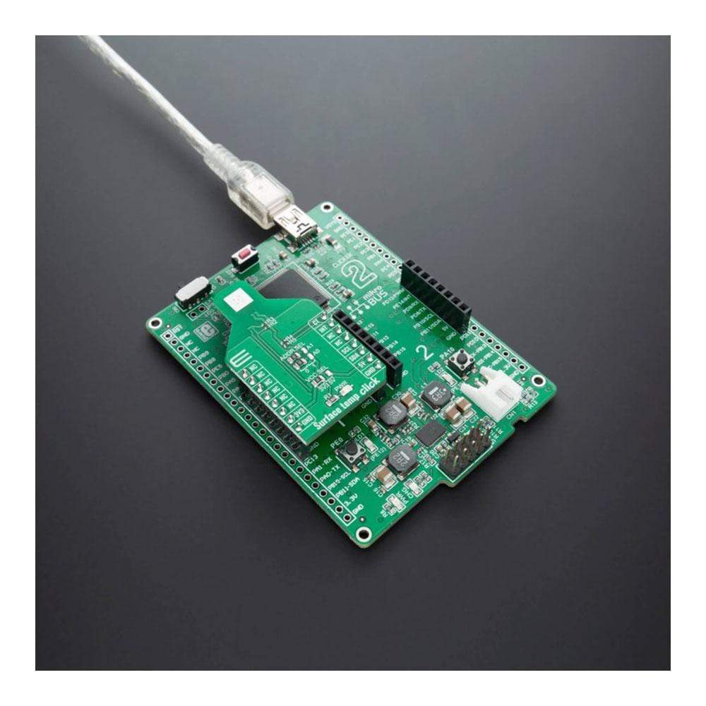
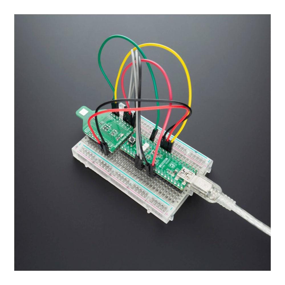
Le Surface Temp Click Board™ est un capteur de température numérique haute précision Click Board™, offrant des performances révolutionnaires sur une large gamme industrielle. Il est équipé de l'ADT7420 - un capteur de température numérique I2C 16 bits précis d'Analog Devices. Il offre une précision de température élevée, une dérive de température ultra-faible (0,0073 °C), une première conversion de température rapide à la mise sous tension, aucun étalonnage/correction de température requis et d'autres fonctionnalités utiles qui font de ce Click Board™ un excellent choix pour le remplacement des RTD et des thermistances, les équipements médicaux, le transport et le stockage des aliments, la surveillance de l'environnement, le CVC et bien d'autres encore.
How Does The Surface Temp Click Board™ Work?
The Surface Temp Click Board™ is based around the ADT7420 which has a 16-bit ADC to monitor and digitize the temperature to 0.0078°C resolution. The ADC resolution, by default, is set to 13 bits (0.0625°C) and is a user programmable mode that can be changed through the serial interface.
The ADT7420 is guaranteed to operate over supply voltages from 2.7 V to 5.5 V. Operating at 3.3 V, the average supply current is typically 210 μA. The ADT7420 has a shutdown mode that powers down the device and offers a shutdown current of typically 2.0 μA at 3.3 V. The ADT7420 is rated for operation over the −40°C to +150°C temperature range.
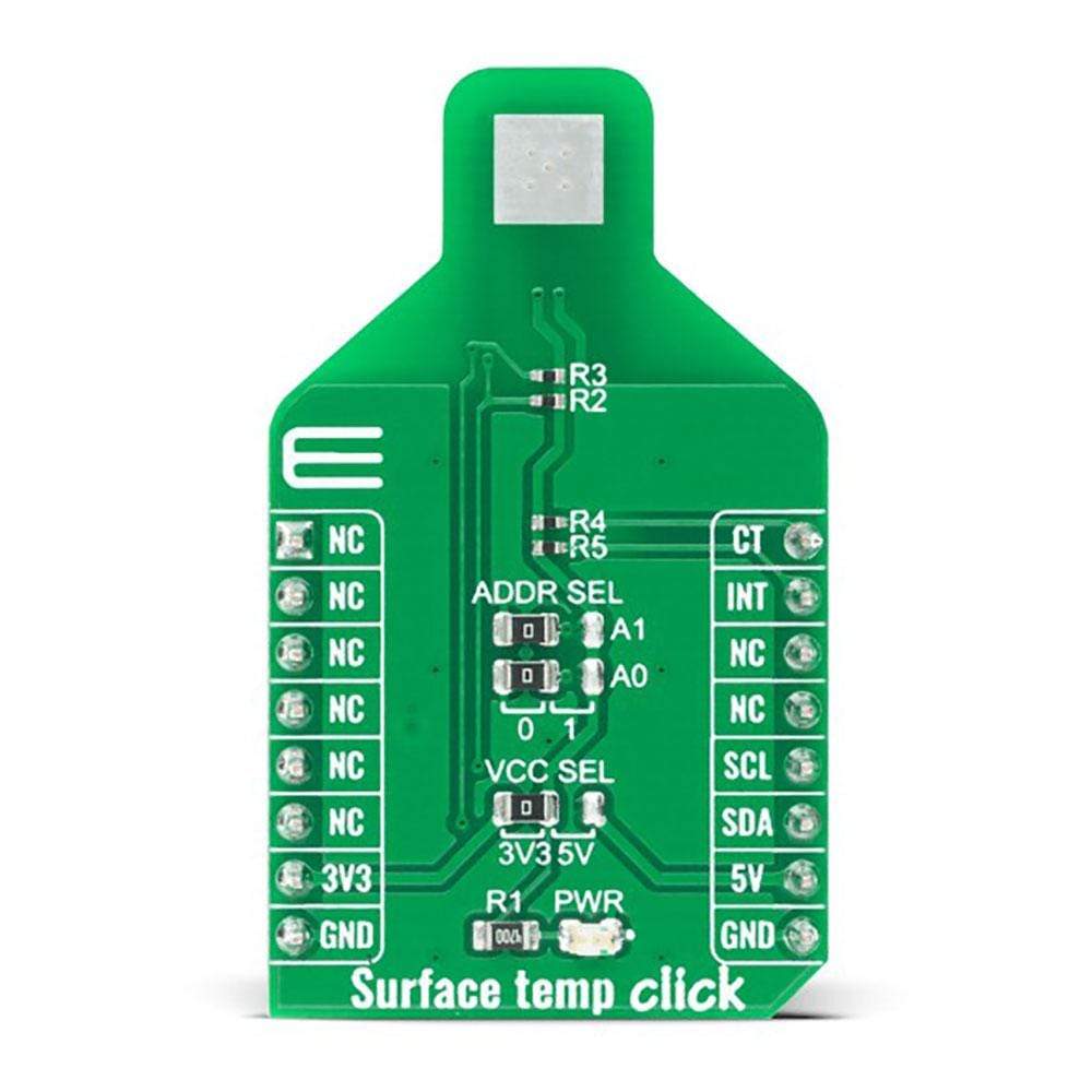
The Surface Temp Click Board™ have a sensing pad, which is thermally connected to a ADT7420, for temperature sensing. The internal temperature sensor has high accuracy and linearity over the entire rated temperature range without needing correction or calibration by the user.
In normal mode (default power-up mode) the ADT7420 runs an automatic conversion sequence. During this automatic conversion sequence, a conversion typically takes 240 ms to complete and the ADT7420 is continuously converting. This means that as soon as one temperature conversion is completed, another temperature conversion begins. Each temperature conversion result is stored in the temperature value registers and is available through the I2C interface. In continuous conversion mode, the read operation provides the most recent converted result.
Like most I2C-compatible devices, the ADT7420 has a 7-bit serial address. The address can be selected by JP2 and JP3 jumpers (details in ADT7420 datasheet). Pin A0 and Pin A1 are available for address selection, giving the ADT7420 four possible I2C addresses.
The INT and CT pins have two under-temperature/over-temperature modes: comparator mode and interrupt mode. The interrupt mode is the default power-up overtemperature mode. The CT pin is an open-drain output that becomes active when the temperature exceeds a programmable critical temperature limit. The INT pin is also an open-drain output that becomes active when the temperature exceeds a programmable limit. The INT pin and CT pin can operate in comparator and interrupt event modes.
The voltage range which can be used to power up the Surface Temp Click Board™, allows it to work with controllers which have GPIO on both 3.3V and 5V. It can be selected by soldering a small SMD jumper, labelled as VCC SEL to the correct position. As well as PWR LED indicator for signaling that power is present on the system.
SPECIFICATIONS
Type | Temperature |
Applications | RTD and thermistor replacement, Thermocouple cold junction compensation, Medical equipment, Industrial control and test, Food transportation and storage, Environmental monitoring and HVAC, Laser diode temperature control. Programmable interrupts. Low power. |
On-board modules | ADT7420 |
Key Features | High accuracy digital temperature sensor offering breakthrough performance over a wide industrial range. 16-bit ADC to monitor and digitize the temperature to 0.0078°C resolution. |
Interface | I2C |
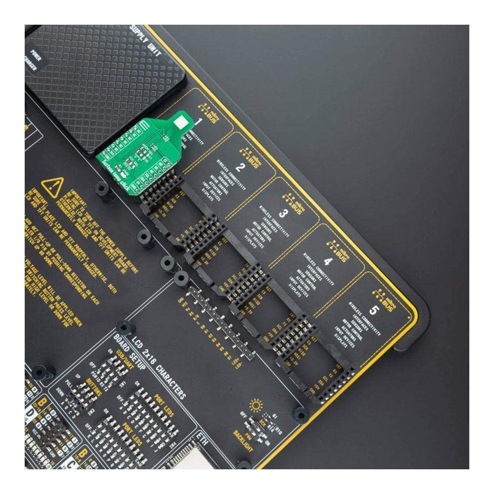
Compatibility | mikroBUS |
Click board size | M (42.9 x 25.4 mm) |
Input Voltage | 3.3V or 5V |
PINOUT DIAGRAM
Notes | Pin | Pin | Notes | ||||
---|---|---|---|---|---|---|---|
NC | 1 | AN | PWM | 16 | CT | Critical Overtemp Indicator | |
NC | 2 | RST | INT | 15 | INT | Overtemp and Undertemp Indicator | |
NC | 3 | CS | RX | 14 | NC | ||
NC | 4 | SCK | TX | 13 | NC | ||
NC | 5 | MISO | SCL | 12 | SCL | I2C Clock | |
NC | 6 | MOSI | SDA | 11 | SDA | I2C Data | |
Power Supply | 3.3V | 7 | 3.3V | 5V | 10 | 5V | Power Supply |
Ground | GND | 8 | GND | GND | 9 | GND | Ground |
ONBOARD SETTINGS AND INDICATORS
Label | Name | Default | Description |
---|---|---|---|
LD1 | PWR | - | Power LED Indicator |
JP1 | VCC SEL | Left | Power supply voltage selection: left position 3V3, right position 5V |
JP2 | PWR | Left | Slave address selection: Left position 0, right position 1 |
J3 | PWR | Left | Slave address selection: Left position 0, right position 1 |
SURFACE TEMP CLICK ELECTRICAL SPECIFICATIONS
Description | Min | Typ | Max | Unit |
---|---|---|---|---|
Supply Voltage | 2.7 | - | 5.5 | V |
Temperature accuracy from −20°C to +105°C | - | ±0.25 | - | °C |
Temperature drift | - | 0.0073 | - | °C |
Power consumption at 3.3 V in normal mode | - | 700 | - | µW |
Power consumption at 3.3 V in shutdown mode | - | 7 | - | µW |
Resolution | - | 16 | - | bit |
Software Support
We provide a library for the Surface Temp Click Board™ on our LibStock page, as well as a demo application (example), developed using MikroElektronika compilers. The demo can run on all the main MikroElektronika development boards.
Library Description
The library contains basic functions for working with Surface temp Click Board™.
Key Functions
float surfacetemp_get_temperature ( void )
- Getting temperature value.uint8_t surfacetemp_get_status ( void )
- Getting device status.uint8_t surfacetemp_setup ( void )
- Device initialization.
Example Description
The application is composed of three sections :
- System Initialization - Initializes INT pin, PWM pin, I2C module and LOG module.
- Application Initialization - Initializes I2C driver, Click Board™ board and sets thresholds.
- Application Task - Reads temperature value and value log on the USBUART.
void application_task ( ) { float temperature; char demo_text[ 20 ]; temperature = surfacetemp_get_temperature( ); FloatToStr( temperature, demo_text ); mikrobus_logWrite( "> Temperature : ", _LOG_TEXT ); mikrobus_logWrite( demo_text, _LOG_LINE ); Delay_ms( 1500 ); }
The full application code, and ready to use projects can be found on our LibStock page.
Other mikroE Libraries used in the example:
- I2C
- UART
Additional Notes and Information
Depending on the development board you are using, you may need USB UART Click Board™, USB UART 2 Click Board™ or RS232 Click Board™ to connect to your PC, for development systems with no UART to USB interface available on the board. The terminal available in all MikroElektronika compilers, or any other terminal application of your choice, can be used to read the message.
MIKROSDK
The Surface Temp Click Board™ is supported with mikroSDK - MikroElektronika Software Development Kit. To ensure proper operation of mikroSDK compliant Click board™ demo applications, mikroSDK should be downloaded from the LibStock and installed for the compiler you are using.
Carte de clic de température de surface
Frequently Asked Questions
Have a Question?
Be the first to ask a question about this.