


Mikroelektronika d.o.o.
Carte Click esclave M-Bus
Carte Click esclave M-Bus
SKU: MIKROE-4137
Impossible de charger la disponibilité du service de retrait


Overview
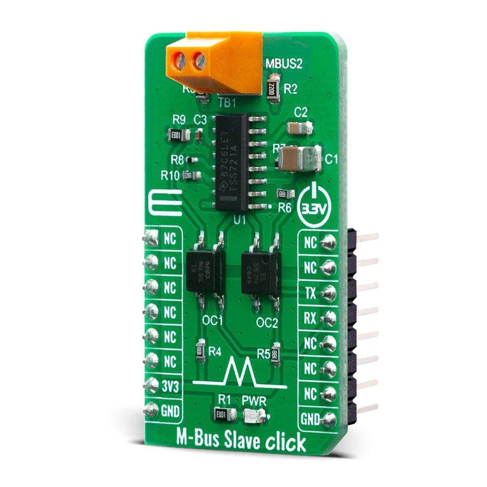
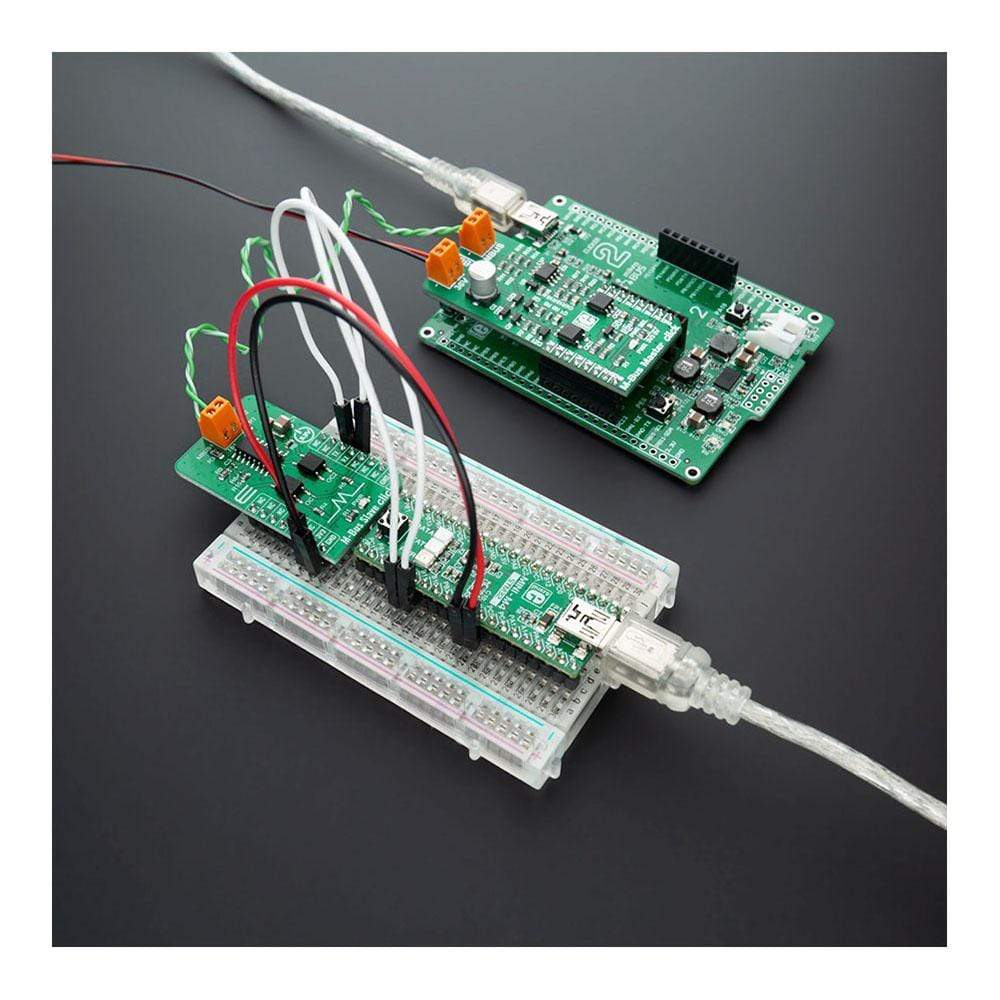
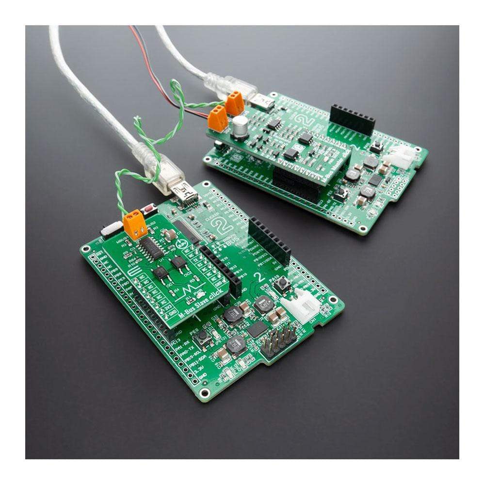
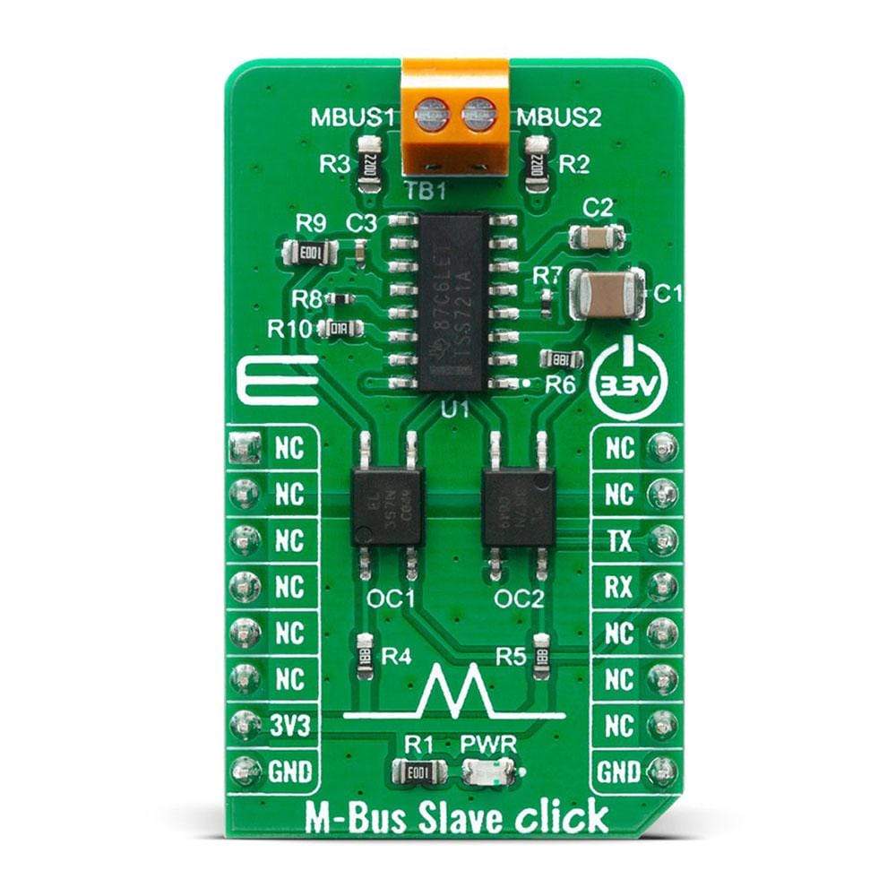
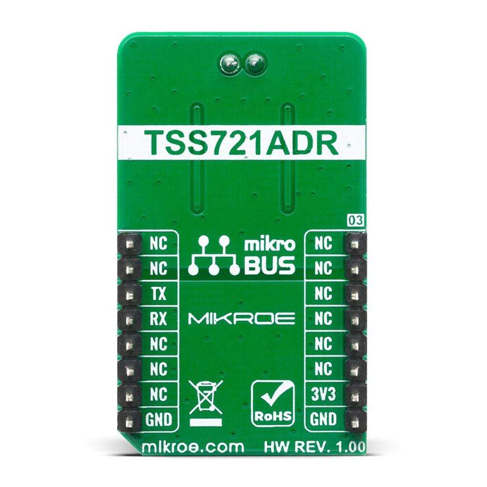
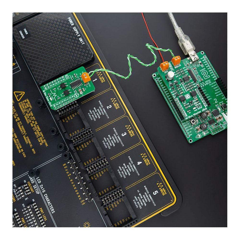
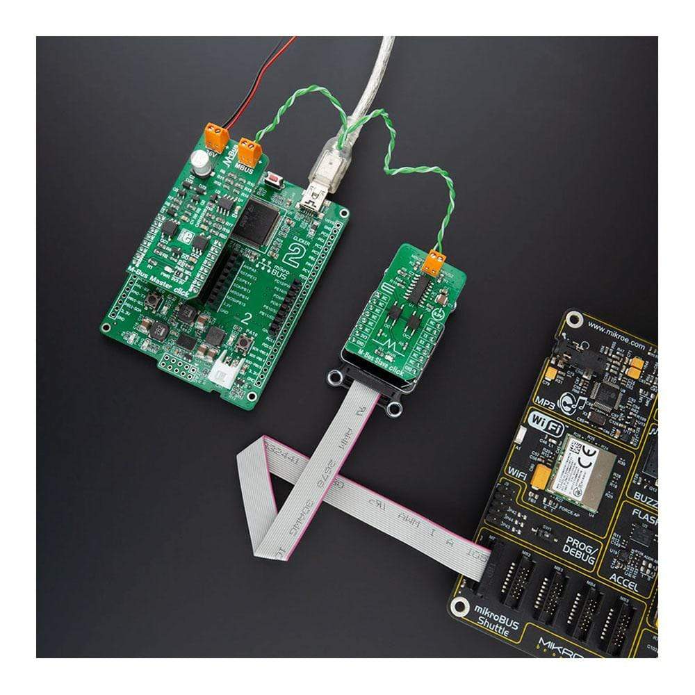
The M-Bus Slave Click Board™ is equipped with the TSS721A, a single chip transceiver developed by Texas Instruments for Meter-Bus applications according to EN1434-3 standard. The connection to the bus is polarity independent and serves as a slave node in the system.
The M-Bus Slave Click Board™ has full galvanic isolation with optocouplers to improve the reliability of the whole circuit. The circuit is supplied by the master via the bus. Therefore, this circuit offers no additional load for the slave battery. The TSS721A has a power-fail function integrated within. This solution is perfect for a plethora of applications like remote reading of gas, water, heat or electricity, or other types of consumption meters.
Downloads
La carte Click Board M-Bus Slave™ est équipé du TSS721A, un émetteur-récepteur monopuce développé par Texas Instruments pour les applications Meter-Bus selon la norme EN1434-3. La connexion au bus est indépendante de la polarité et sert de nœud esclave dans le système.
Le M-Bus Slave Click Board™ est doté d'une isolation galvanique complète avec optocoupleurs pour améliorer la fiabilité de l'ensemble du circuit. Le circuit est alimenté par le maître via le bus. Par conséquent, ce circuit n'offre aucune charge supplémentaire pour la batterie esclave. Le TSS721A dispose d'une fonction de coupure de courant intégrée. Cette solution est parfaite pour une multitude d'applications telles que la lecture à distance de compteurs de gaz, d'eau, de chaleur ou d'électricité, ou d'autres types de compteurs de consommation.
| General Information | |
|---|---|
Part Number (SKU) |
MIKROE-4137
|
Manufacturer |
|
| Physical and Mechanical | |
Weight |
0.018 kg
|
| Other | |
EAN |
8606018717767
|
Frequently Asked Questions
Have a Question?
Be the first to ask a question about this.