


Mikroelektronika d.o.o.
Tableau de clic 9DOF 2
Tableau de clic 9DOF 2
SKU: MIKROE-4128
Impossible de charger la disponibilité du service de retrait


Overview
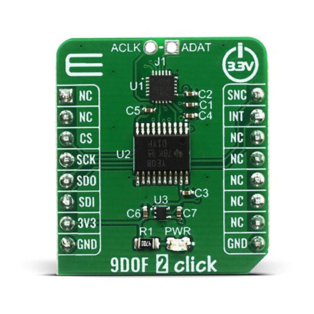
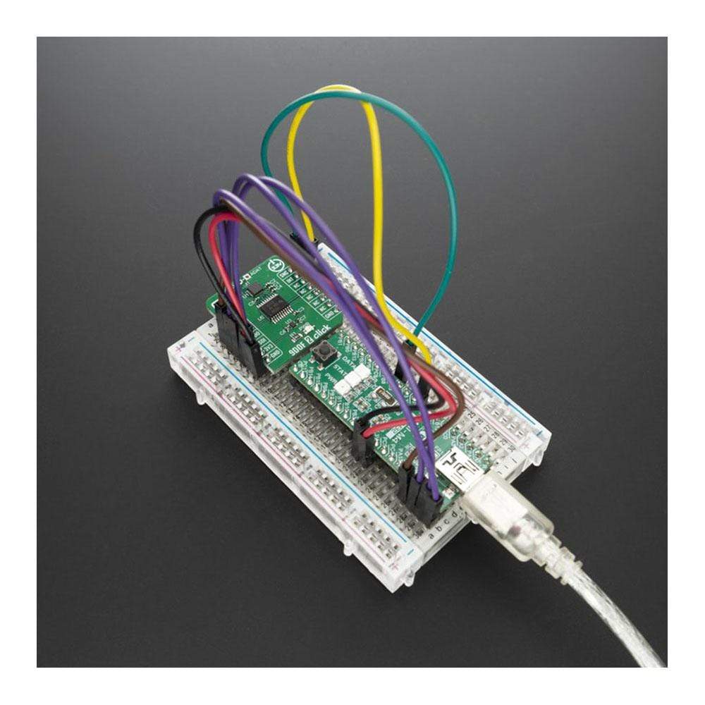
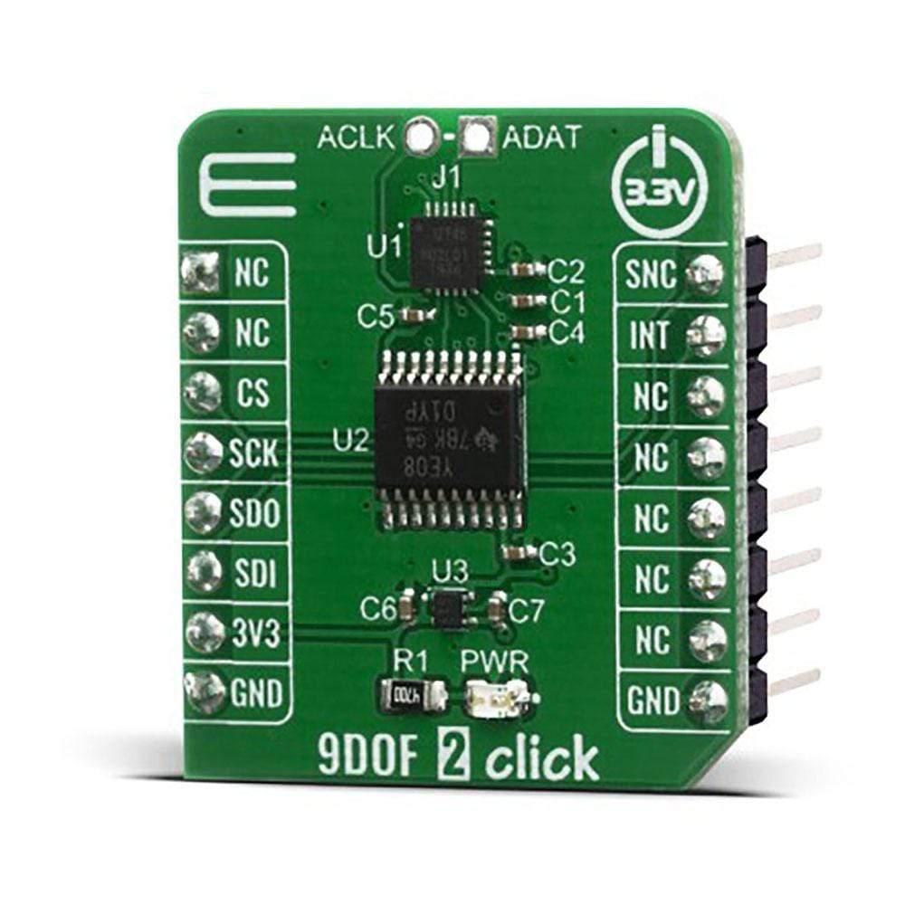
The 9DOF 2 Click Board™ is a compact add-on board for applications that require the lowest power motion tracking and magnetometer functionality. This board features the ICM-20948 a 9-axis MotionTracking™ sensor from TDK Invensense, which consist of two sensors combined into one package for a universal 9DOF solution. In this package, we have a 3-axis gyroscope, a 3-axis accelerometer, a 3-axis magnetometer, combined with Digital Motion Processor™ (DMP) and run-time calibration firmware. All these features make the 9DOF 2 Click Board™ an excellent choice for manufacturers looking for a product to eliminate the costly and complex selection, qualification, and system-level integration of discrete devices, guaranteeing optimal motion performance for consumers. Its also ideally suited for wearable sensors and IoT applications needed low power motion tracking device expandable with additional I2C sensors.
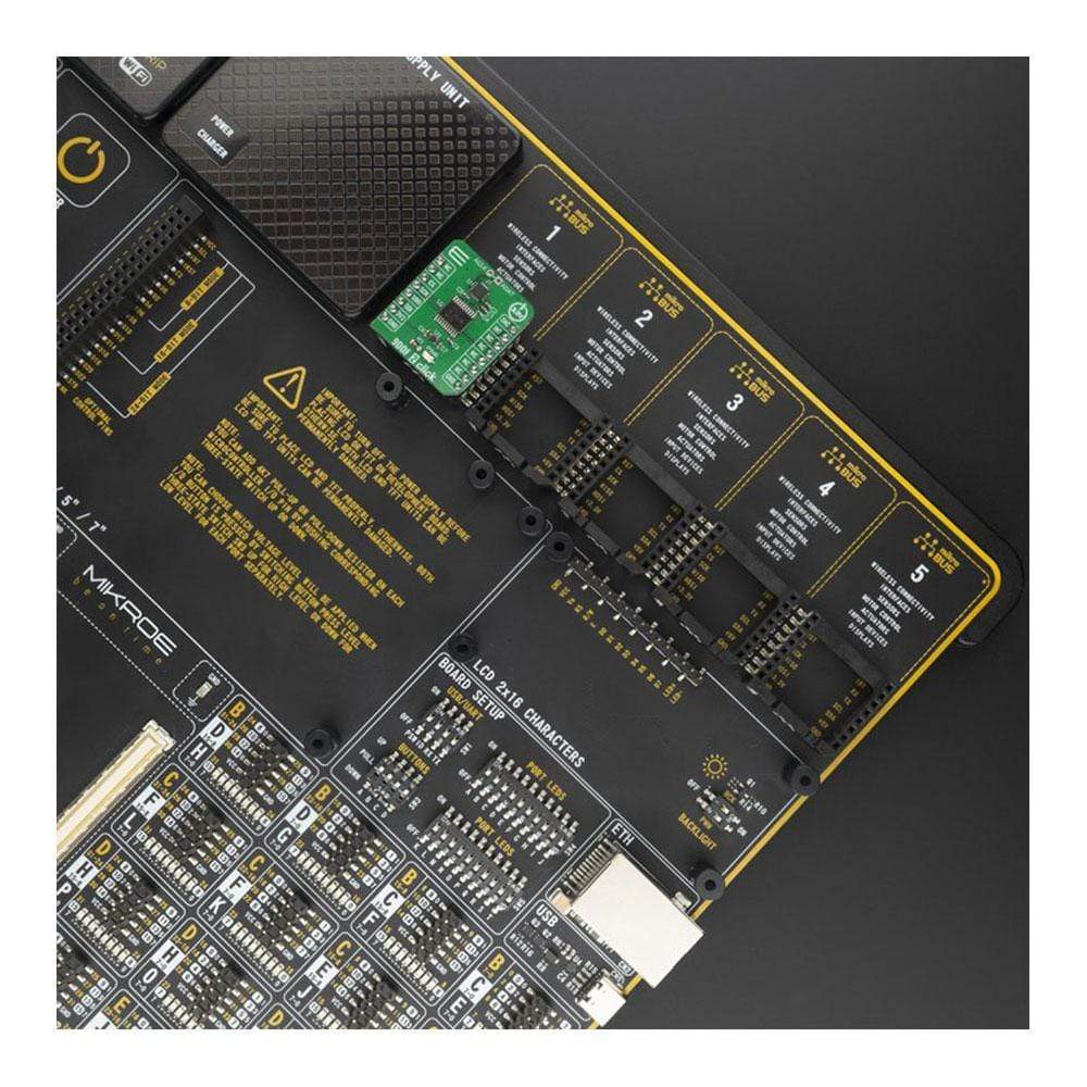
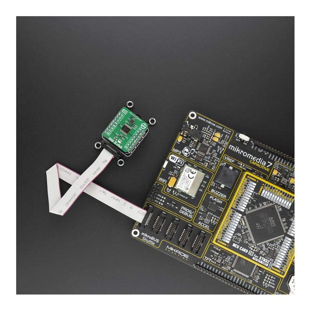
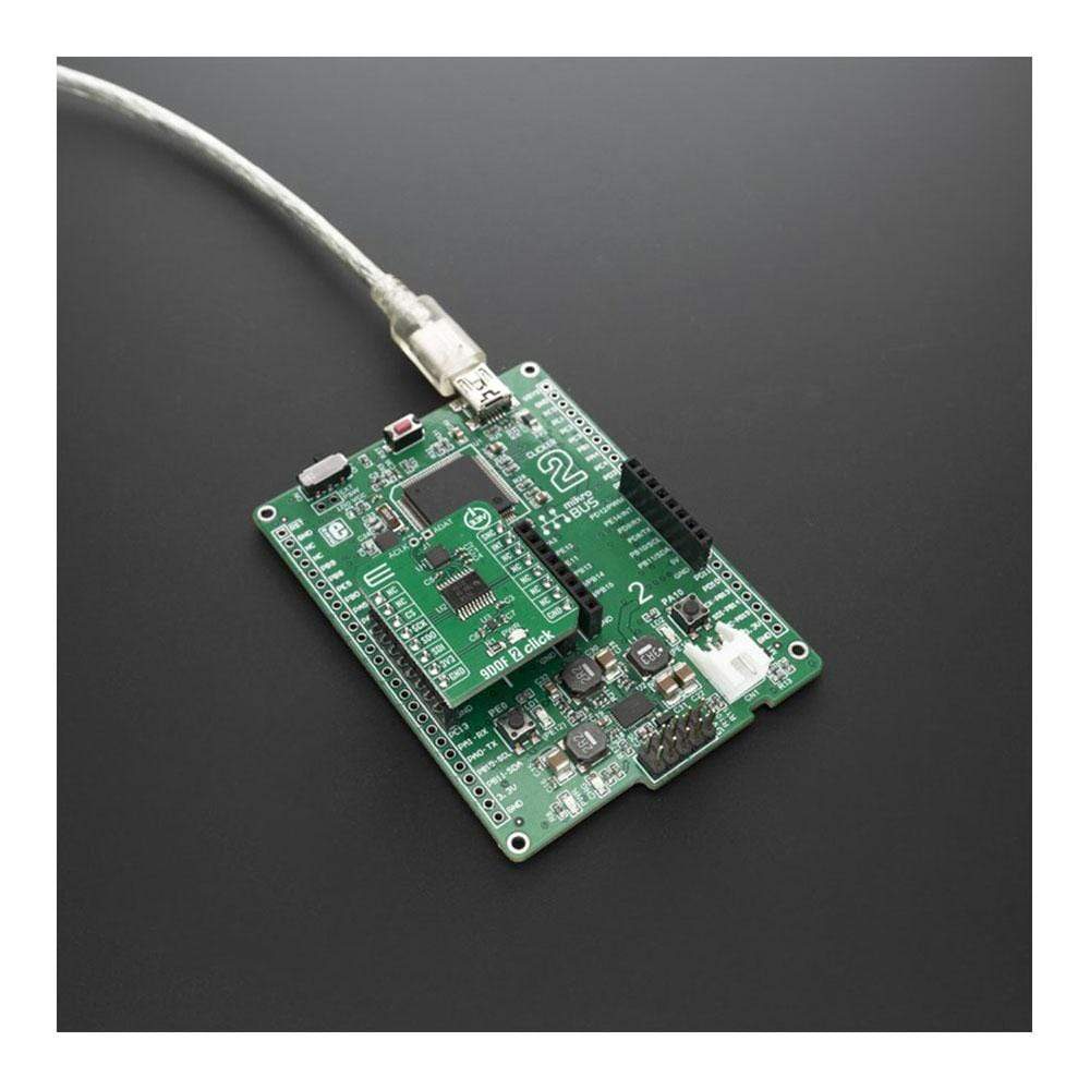
The 9DOF 2 Click Board™ is supported by a mikroSDK compliant library, which includes functions that simplify software development. This Click Board™ comes as a fully tested product, ready to be used on a system equipped with the mikroBUS™ socket.
Downloads
Le Click Board 9DOF 2™ est une carte complémentaire compacte pour les applications qui nécessitent la fonctionnalité de suivi de mouvement et de magnétomètre à faible consommation d'énergie. Cette carte comprend le capteur MotionTracking™ à 9 axes ICM-20948 de TDK Invensense, qui se compose de deux capteurs combinés dans un seul boîtier pour une solution 9DOF universelle. Dans ce package, nous avons un gyroscope à 3 axes, un accéléromètre à 3 axes, un magnétomètre à 3 axes, combinés à un processeur de mouvement numérique (DMP) et un micrologiciel d'étalonnage en temps réel. Toutes ces fonctionnalités font de la 9DOF 2 Click Board™ un excellent choix pour les fabricants à la recherche d'un produit pour éliminer la sélection, la qualification et l'intégration au niveau du système coûteuses et complexes des appareils discrets, garantissant des performances de mouvement optimales pour les consommateurs. Il est également parfaitement adapté aux capteurs portables et aux applications IoT nécessitant un dispositif de suivi de mouvement à faible consommation extensible avec des capteurs I2C supplémentaires.
La carte Click Board™ 9DOF 2 est prise en charge par une bibliothèque compatible mikroSDK, qui comprend des fonctions qui simplifient le développement logiciel. Cette carte Click Board™ est un produit entièrement testé, prêt à être utilisé sur un système équipé du socket mikroBUS™.
| General Information | |
|---|---|
Part Number (SKU) |
MIKROE-4128
|
Manufacturer |
|
| Physical and Mechanical | |
Weight |
0.018 kg
|
| Other | |
EAN |
8606018717538
|
Frequently Asked Questions
Have a Question?
Be the first to ask a question about this.