


Mikroelektronika d.o.o.
Carte à clic Stepper 14
Carte à clic Stepper 14
SKU: MIKROE-4125
Impossible de charger la disponibilité du service de retrait
Overview
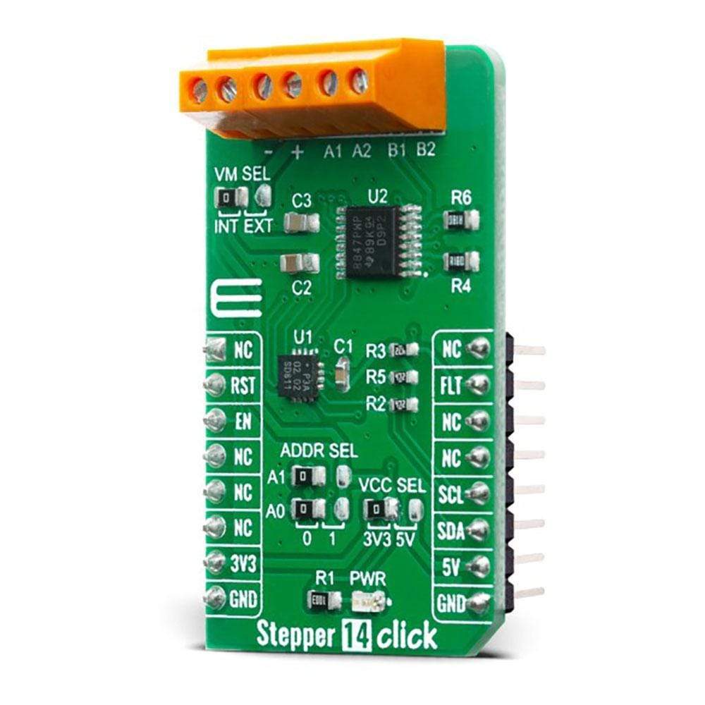
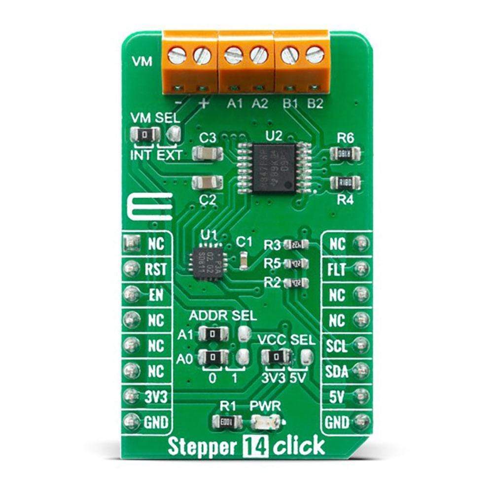
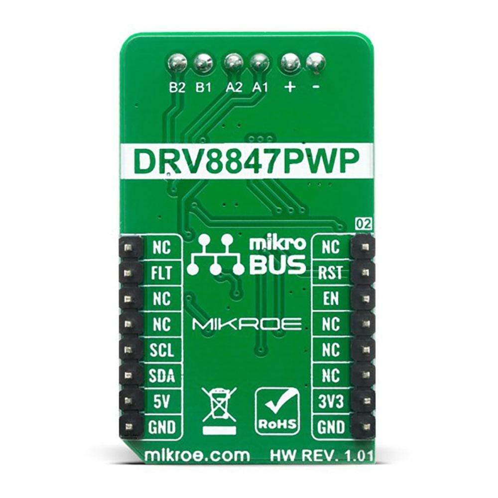
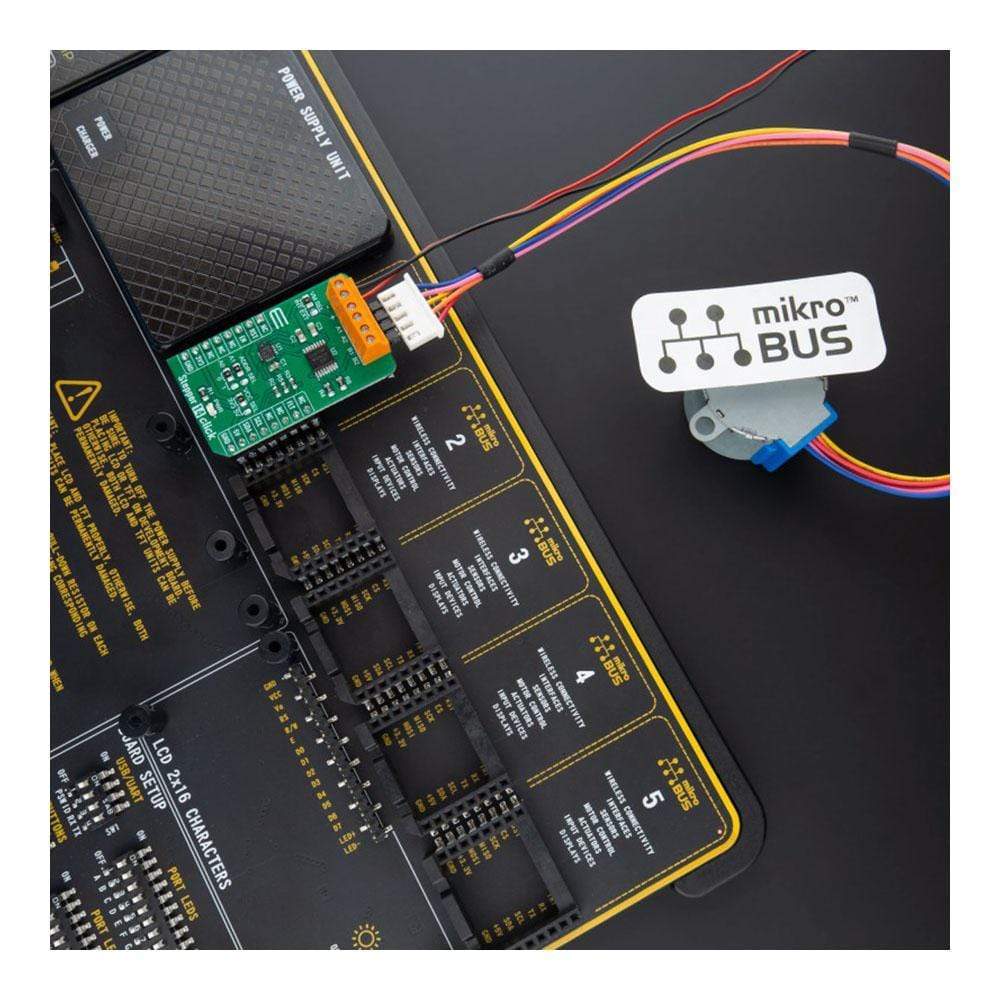
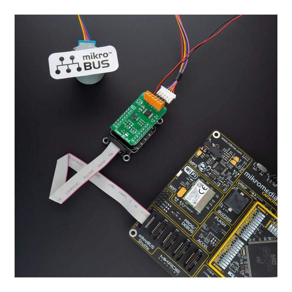
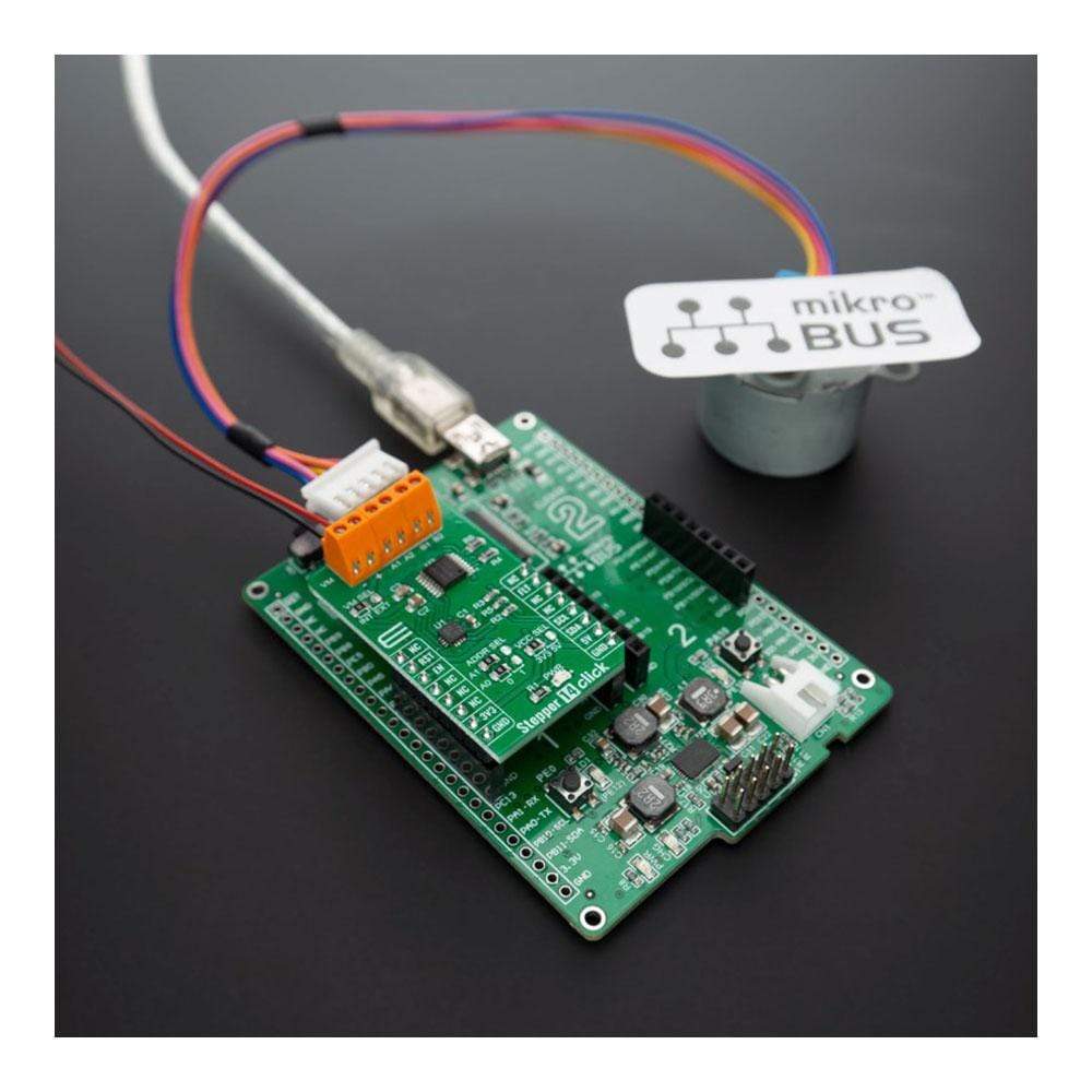
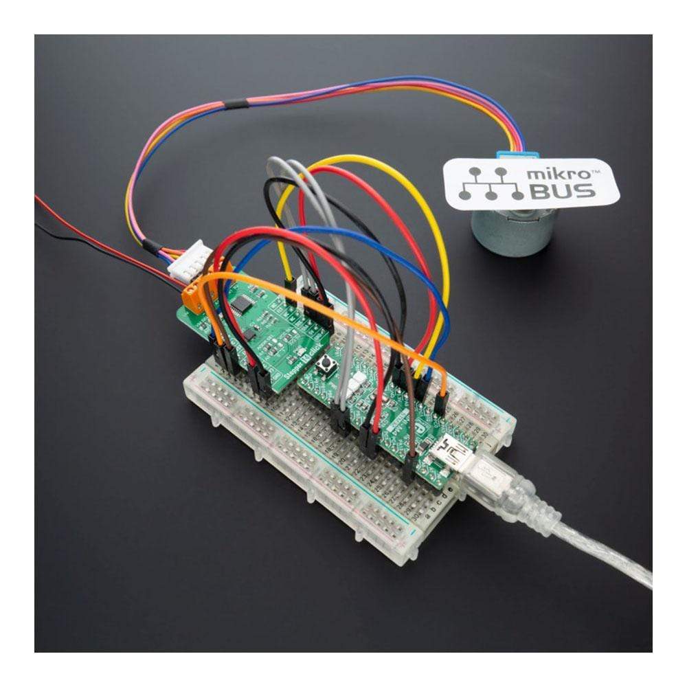
The Stepper 14 Click Board™ features the DRV8847PWPR, a step motor driver, from Texas Instruments. This Click Board™ provides a bipolar step motor controle, It features an H-bridge bipolar step motor driver, which supports full-, half-, quarter-, or eighth-step modes. This Click Board™ also carries a port expander so that the communication can be done with a minimal number of pins, through the mikroBUS™ I2C bus.
The Stepper 14 Click Board™ offers thermal protection, integrated kickback voltage protection, it has a wide range of input voltage, protection against current shoot-through the H-Bridge and high current capability. These features make Stepper 14 Click Board™ an ideal solution for driving motors in any application that demands a precise and safe step motor driver.
Downloads
Le Stepper 14 Click Board™ est équipé du DRV8847PWPR, un pilote de moteur pas à pas, de Texas Instruments. Ce Click Board™ permet un contrôle bipolaire du moteur pas à pas. Il est équipé d'un pilote de moteur pas à pas bipolaire à pont en H, qui prend en charge les modes pas à pas complet, demi-pas, quart de pas ou huitième de pas. Ce Click Board™ est également équipé d'un extenseur de port afin que la communication puisse être effectuée avec un nombre minimal de broches, via le bus I2C mikroBUS™.
Le Stepper 14 Click Board™ offre une protection thermique, une protection intégrée contre les retours de tension, une large plage de tension d'entrée, une protection contre les surtensions à travers le pont en H et une capacité de courant élevée. Ces caractéristiques font du Stepper 14 Click Board™ une solution idéale pour piloter des moteurs dans toute application qui exige un pilote de moteur pas à pas précis et sûr.
| General Information | |
|---|---|
Part Number (SKU) |
MIKROE-4125
|
Manufacturer |
|
| Physical and Mechanical | |
Weight |
0.019 kg
|
| Other | |
EAN |
8606018717514
|
Frequently Asked Questions
Have a Question?
Be the first to ask a question about this.