


Mikroelektronika d.o.o.
Carte à clic RTC 9
Carte à clic RTC 9
SKU: MIKROE-4121
Impossible de charger la disponibilité du service de retrait
Key Features
Overview
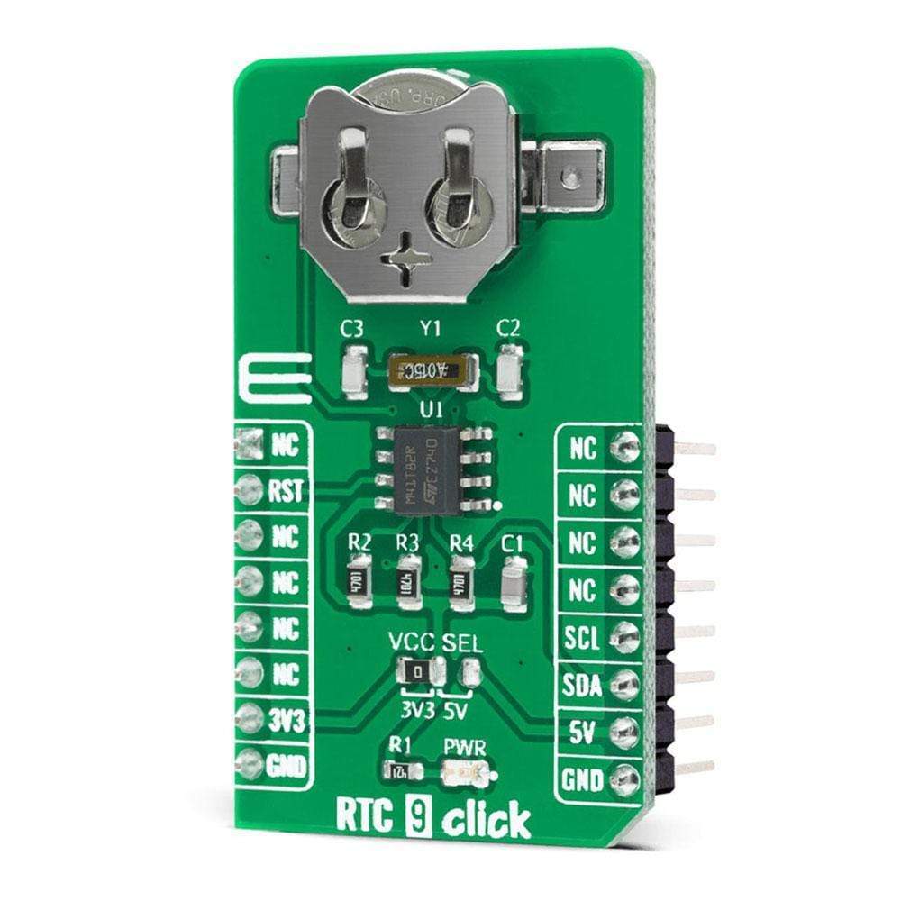
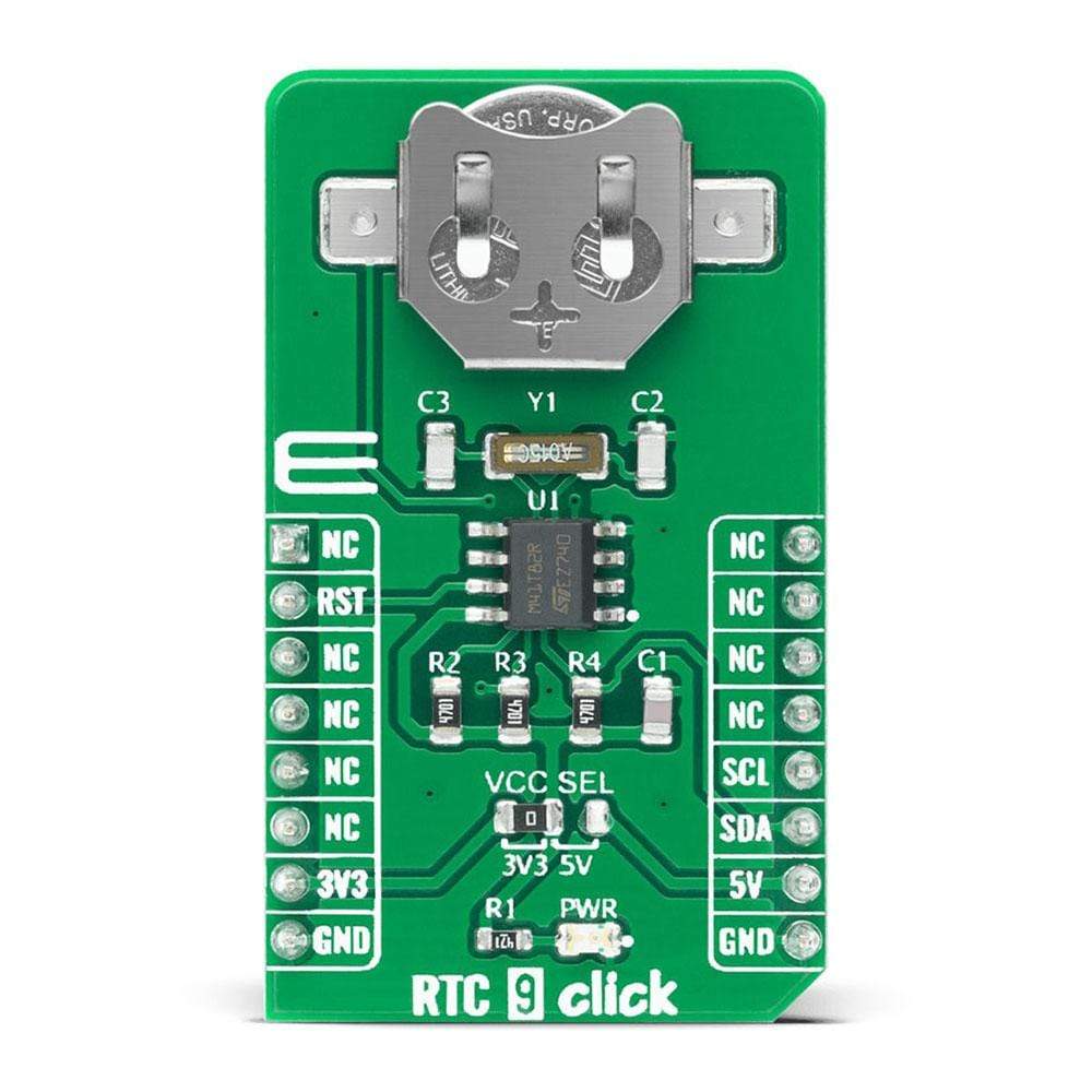
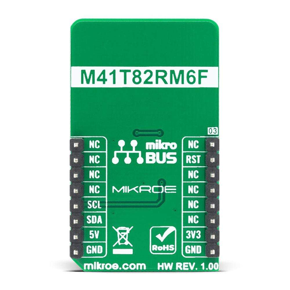
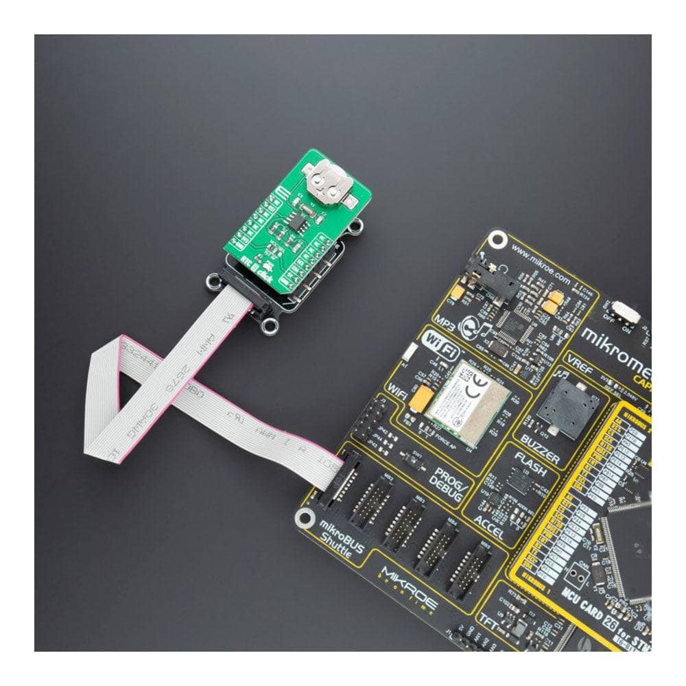
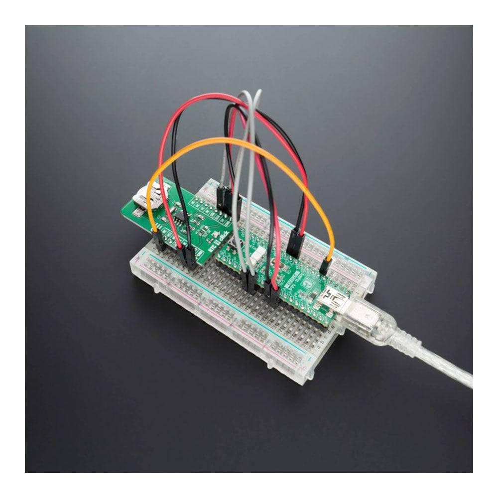
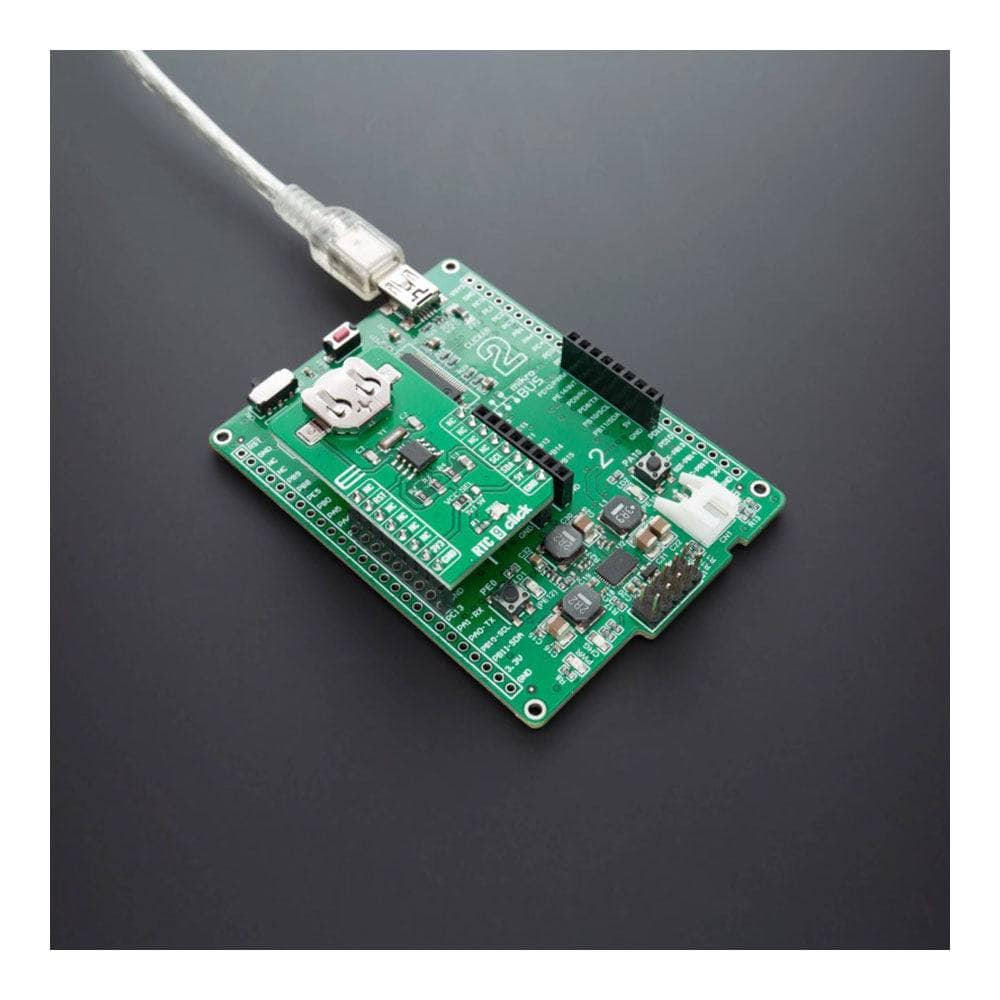
The RTC 9 Click Board™ is a real-time clock module that has an extremely low power consumption, allowing it to be used with a single button cell battery for an extended period of time. This board features the M41T82, real-time clock (RTC) with battery switchover, from ST Microelectronics. It features factory-calibrated accuracy of ±5 ppm typically, automatic switchover and reset output circuitry, programmable alarm with interrupt function, and more.
All these features make RTC 9 Click Board™ an excellent choice for manufacturers for applications such as portable applications, logging devices, wearables, medical equipment, and similar.
Downloads
Le RTC 9 Click Board™ est un module d'horloge en temps réel qui présente une consommation d'énergie extrêmement faible, ce qui lui permet d'être utilisé avec une seule pile bouton pendant une période prolongée. Cette carte est équipée de l'horloge en temps réel (RTC) M41T82 avec commutation de batterie, de ST Microelectronics. Elle offre une précision calibrée en usine de ±5 ppm en général, un circuit de sortie de commutation et de réinitialisation automatique, une alarme programmable avec fonction d'interruption, et bien plus encore.
Toutes ces caractéristiques font du RTC 9 Click Board™ un excellent choix pour les fabricants d'applications telles que les applications portables, les appareils de journalisation, les appareils portables, les équipements médicaux et similaires.
| General Information | |
|---|---|
Part Number (SKU) |
MIKROE-4121
|
Manufacturer |
|
| Physical and Mechanical | |
Weight |
0.019 kg
|
| Other | |
EAN |
8606027380075
|
Frequently Asked Questions
Have a Question?
Be the first to ask a question about this.