


Mikroelektronika d.o.o.
Carte Power MUX Click
Carte Power MUX Click
SKU: MIKROE-4109
Impossible de charger la disponibilité du service de retrait
Overview
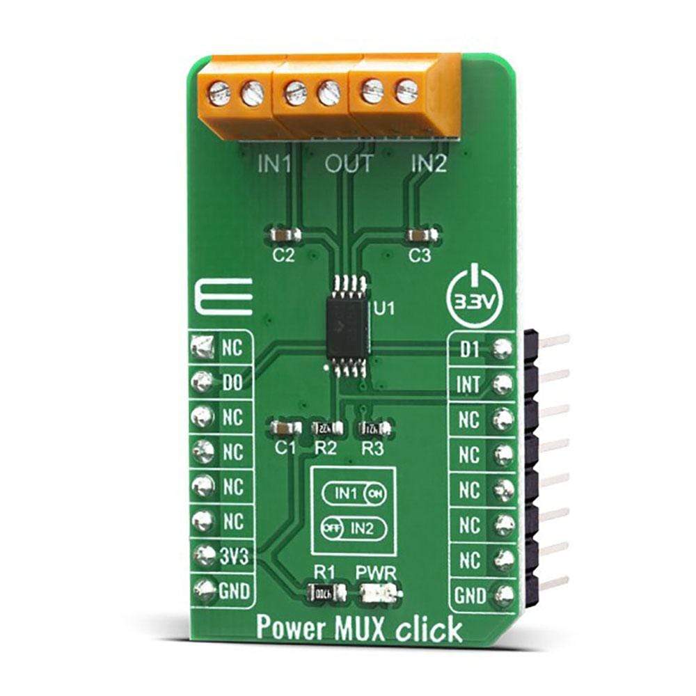
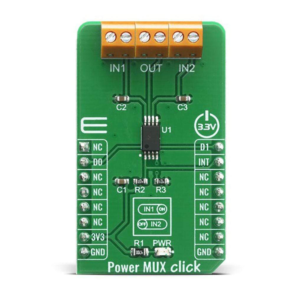
The Power MUX Click Board™ features power multiplexer that enables transition between two power supplies (such as a battery and a wall adapter), each operating at 2.8V to 5.5V and delivering up to 2A current depending on the package. This IC provides inrush current control and thermal protection to the Power MUX Click Board™, manual and auto-switching operating modes, cross-conduction blocking, and reverse-conduction blocking. Operating mode selection depends on a logic level on D0 and D1 pins. Power MUX Click can be used for the transition between two power supplies in applications such as PCs, PDAs, digital cameras, modems, digital radios, MP3 players, and similar applications.
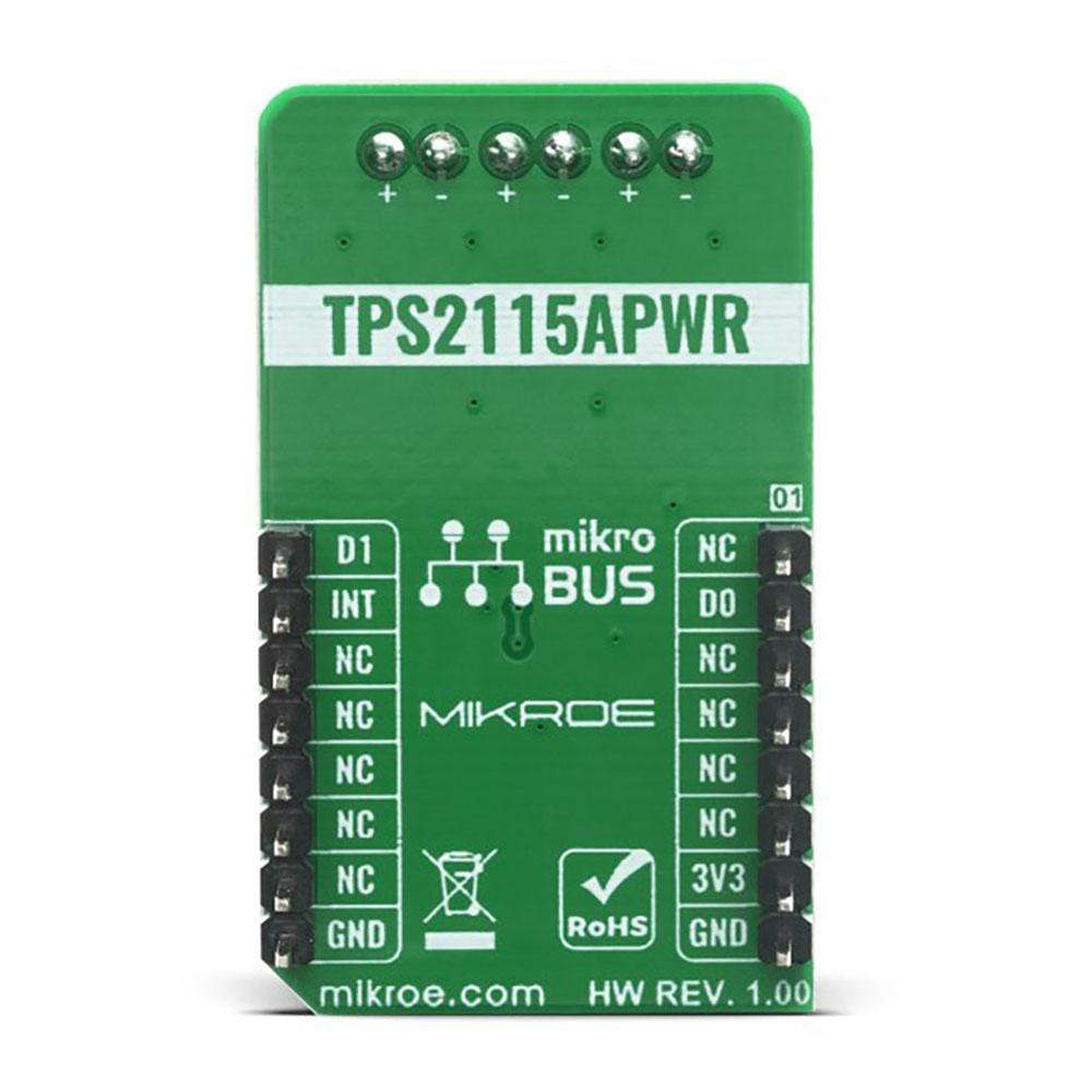
The Power MUX Click Board™ is supported by a mikroSDK compliant library, which includes functions that simplify software development. This Click Board™ comes as a fully tested product, ready to be used on a system equipped with the mikroBUS™ socket.
Downloads
La carte Power MUX Click Board™ est dotée d'un multiplexeur de puissance qui permet la transition entre deux alimentations (comme une batterie et un adaptateur mural), chacune fonctionnant entre 2,8 V et 5,5 V et délivrant jusqu'à 2 A de courant selon le boîtier. Ce circuit intégré fournit un contrôle du courant d'appel et une protection thermique à la carte Power MUX Click Board™ , des modes de fonctionnement à commutation manuelle et automatique, un blocage de conduction croisée et un blocage de conduction inverse. La sélection du mode de fonctionnement dépend d'un niveau logique sur les broches D0 et D1. Power MUX Click peut être utilisé pour la transition entre deux alimentations dans des applications telles que les PC, les PDA, les appareils photo numériques, les modems, les radios numériques, les lecteurs MP3 et des applications similaires.
Le Power MUX Click Board™ est pris en charge par une bibliothèque compatible mikroSDK, qui comprend des fonctions qui simplifient le développement logiciel. Ce Click Board™ est un produit entièrement testé, prêt à être utilisé sur un système équipé du socket mikroBUS™.
| General Information | |
|---|---|
Part Number (SKU) |
MIKROE-4109
|
Manufacturer |
|
| Physical and Mechanical | |
Weight |
0.02 kg
|
| Other | |
EAN |
8606018717545
|
Frequently Asked Questions
Have a Question?
Be the first to ask a question about this.