


Mikroelektronika d.o.o.
Carte à clic ADC 9
Carte à clic ADC 9
SKU: MIKROE-4105
Impossible de charger la disponibilité du service de retrait


Key Features
Overview
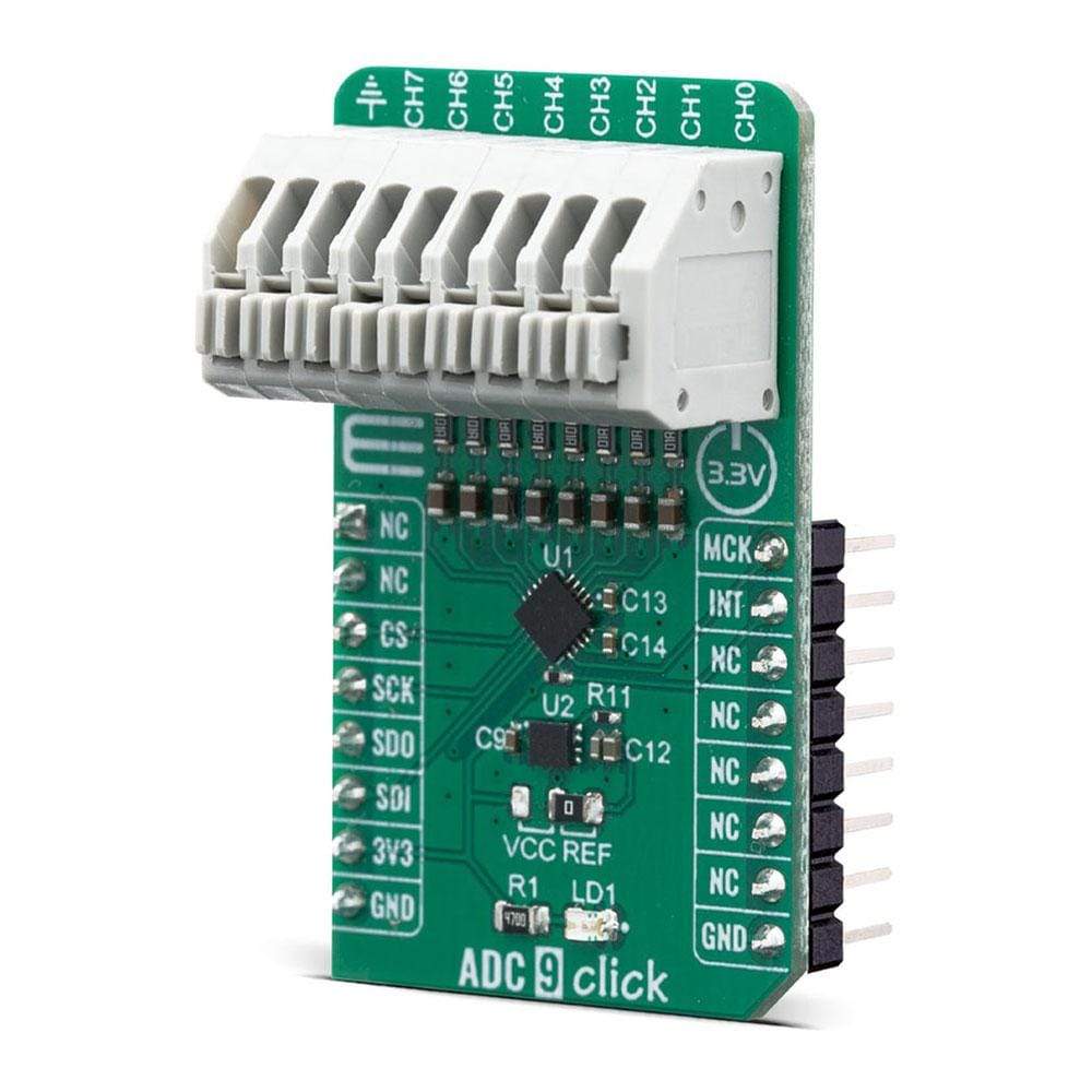
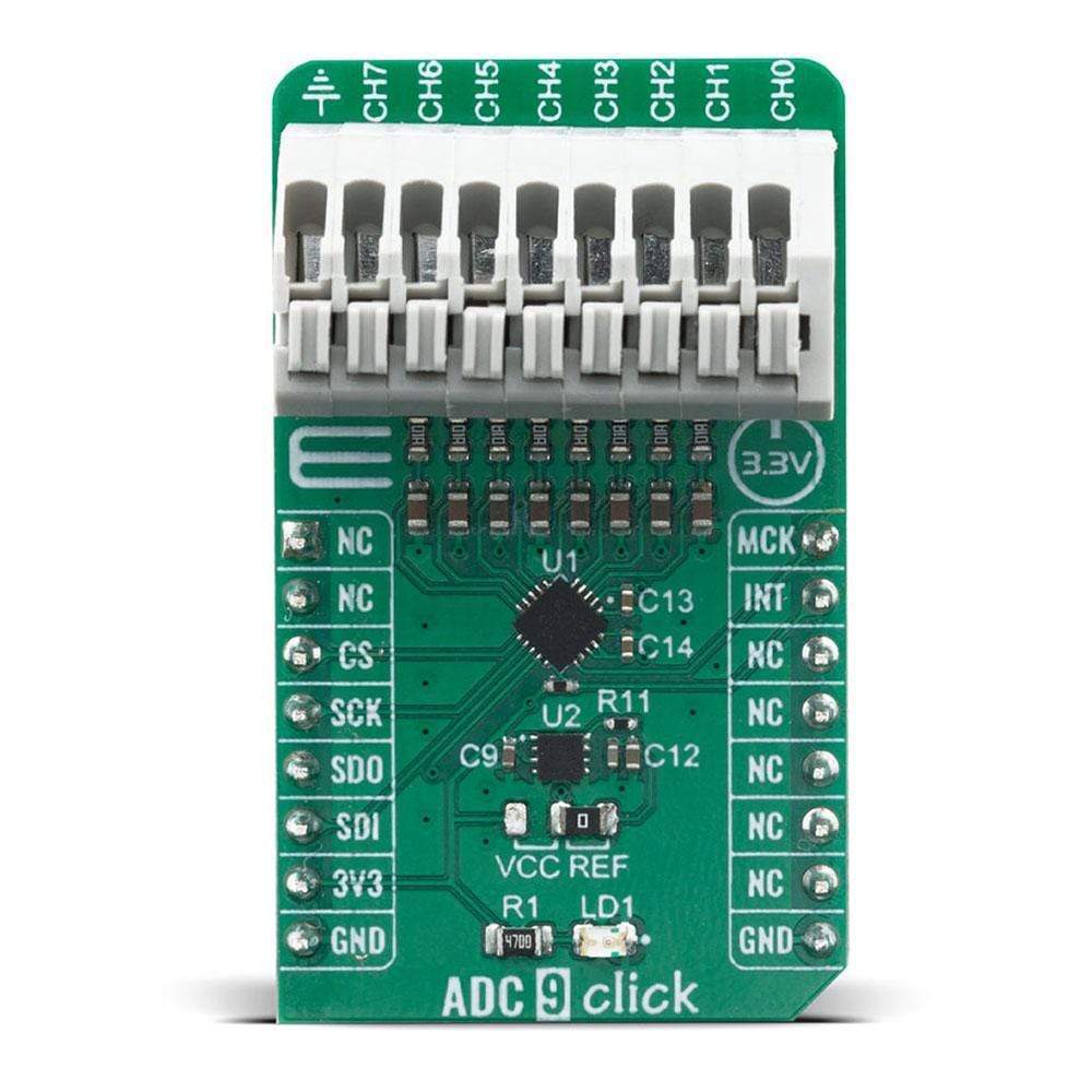
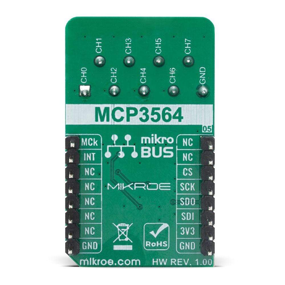
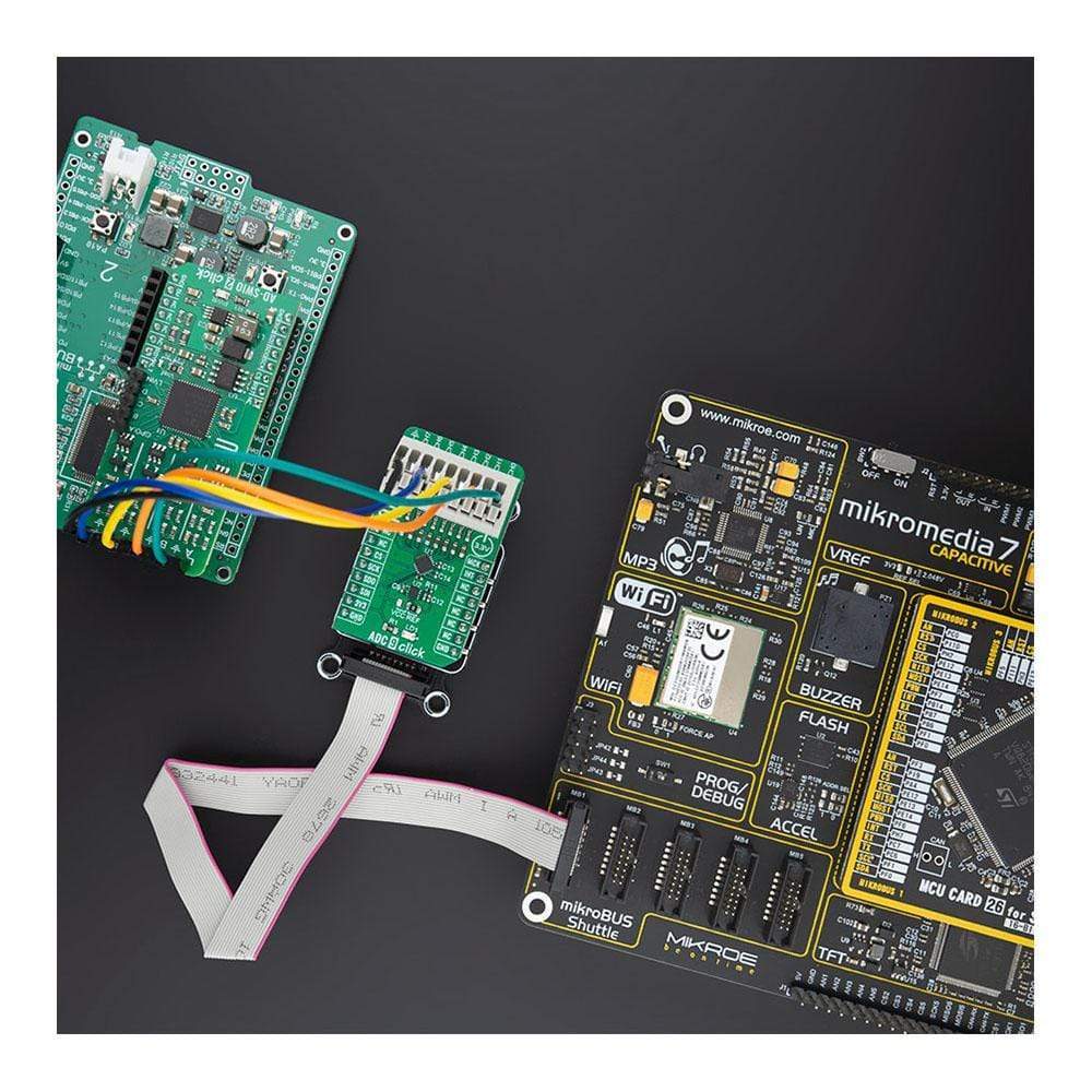
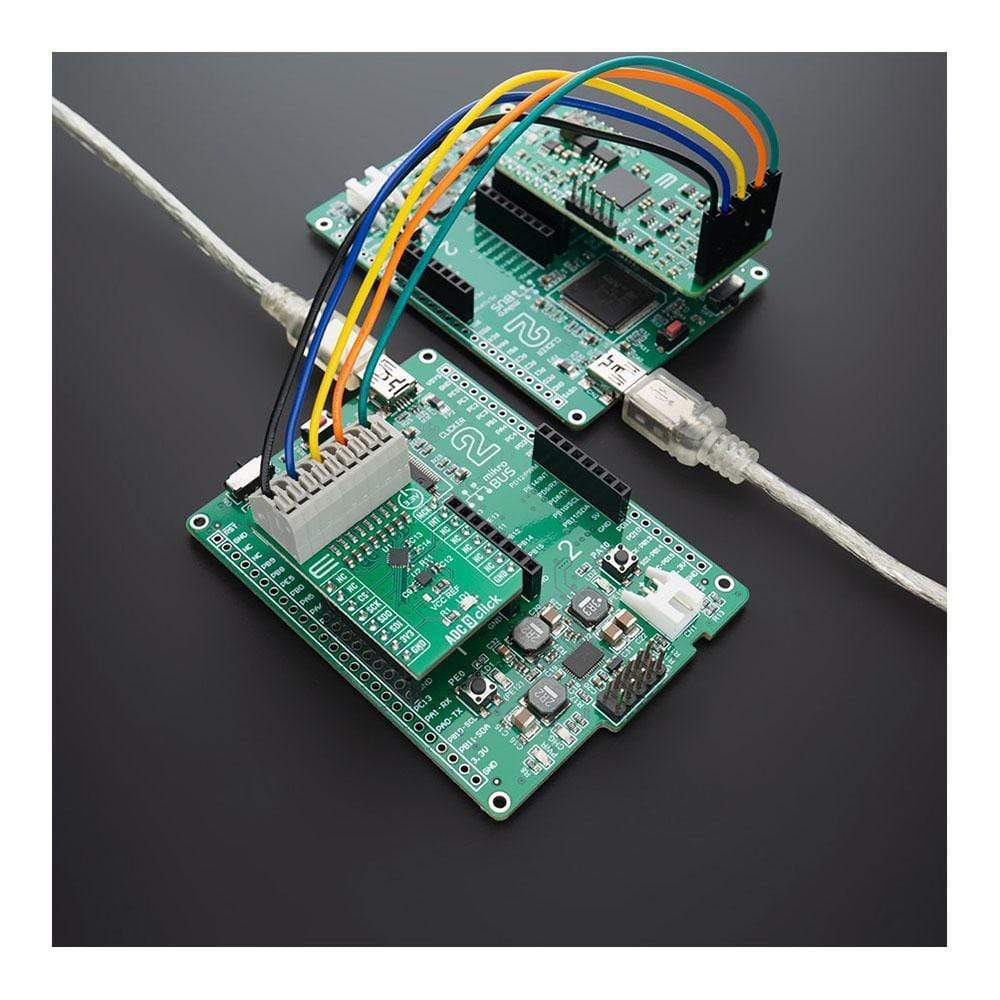
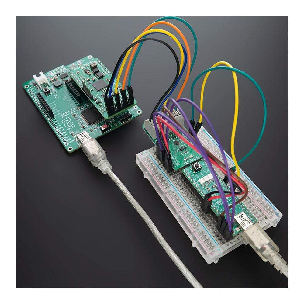
The ADC 9 Click Board™ is the 8th channel analogue to digital converter expansion board, for projects where you have demand for multi-channel ADC conversions such as microcontrollers with a small number or no analogue inputs. This Click board is based on MCP3564 a 24-bit Delta-Sigma Analog-to-Digital Converter with a programmable data rate of up to 153.6 KSPS from Microchip. It offers integrated features, such as an internal oscillator, temperature sensor and burnout sensor detection, in order to reduce system component count and total solution cost. An ideal choice for precision data acquisition systems, high-resolution data converters, industrial control, battery-powered devices and many more.
The ADC 9 Click Board™ is supported by a mikroSDK compliant library, which includes functions that simplify software development. This Click Board™ comes as a fully tested product, ready to be used on a system equipped with the mikroBUS™ socket.
Downloads
Le Carte à clic ADC 9™ est la carte d'extension de convertisseur analogique-numérique à 8 canaux, pour les projets où vous avez besoin de conversions ADC multicanaux tels que les microcontrôleurs avec un petit nombre ou aucune entrée analogique. Cette carte Click est basée sur le MCP3564, un convertisseur analogique-numérique Delta-Sigma 24 bits avec un débit de données programmable jusqu'à 153,6 KSPS de Microchip. Il offre des fonctionnalités intégrées, telles qu'un oscillateur interne, un capteur de température et une détection de capteur de burnout, afin de réduire le nombre de composants du système et le coût total de la solution. Un choix idéal pour les systèmes d'acquisition de données de précision, les convertisseurs de données haute résolution, le contrôle industriel, les appareils alimentés par batterie et bien d'autres.
La carte à clic ADC 9™ est pris en charge par une bibliothèque compatible mikroSDK, qui comprend des fonctions qui simplifient le développement logiciel. Cette Click Board™ est un produit entièrement testé, prêt à être utilisé sur un système équipé du socket mikroBUS™.
| General Information | |
|---|---|
Part Number (SKU) |
MIKROE-4105
|
Manufacturer |
|
| Physical and Mechanical | |
Weight |
0.021 kg
|
| Other | |
EAN |
8606018717385
|
Frequently Asked Questions
Have a Question?
Be the first to ask a question about this.