


Mikroelektronika d.o.o.
Carte à clic ISO ADC
Carte à clic ISO ADC
SKU: MIKROE-4088
Impossible de charger la disponibilité du service de retrait


Overview
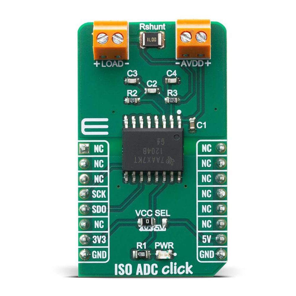
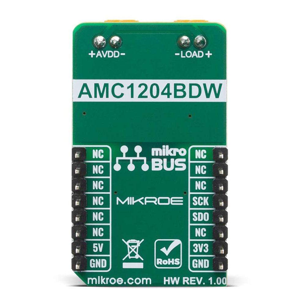
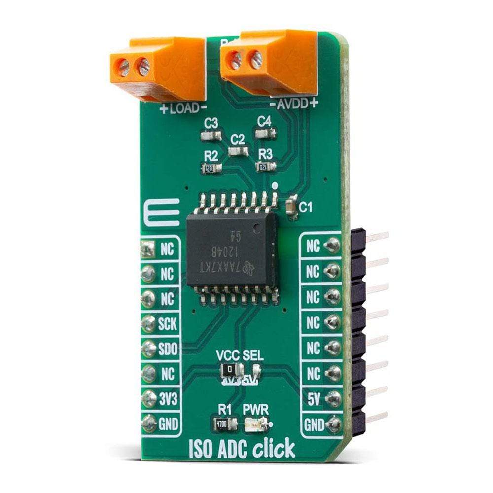
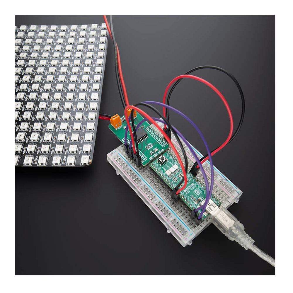
The ISO ADC Click Board™ is add-on board current-shunt measurement device with isolated delta-sigma modulator. This Click Board™ is based on AMC1204BDWR provide a single-chip solution for measuring the small signal of a shunt resistor across an isolated barrier from Texas Instruments. ISO ADC Click contains shunt resistor, these types of resistors are typically used to sense currents in motor control inverters, green energy generation systems, and other industrial applications.
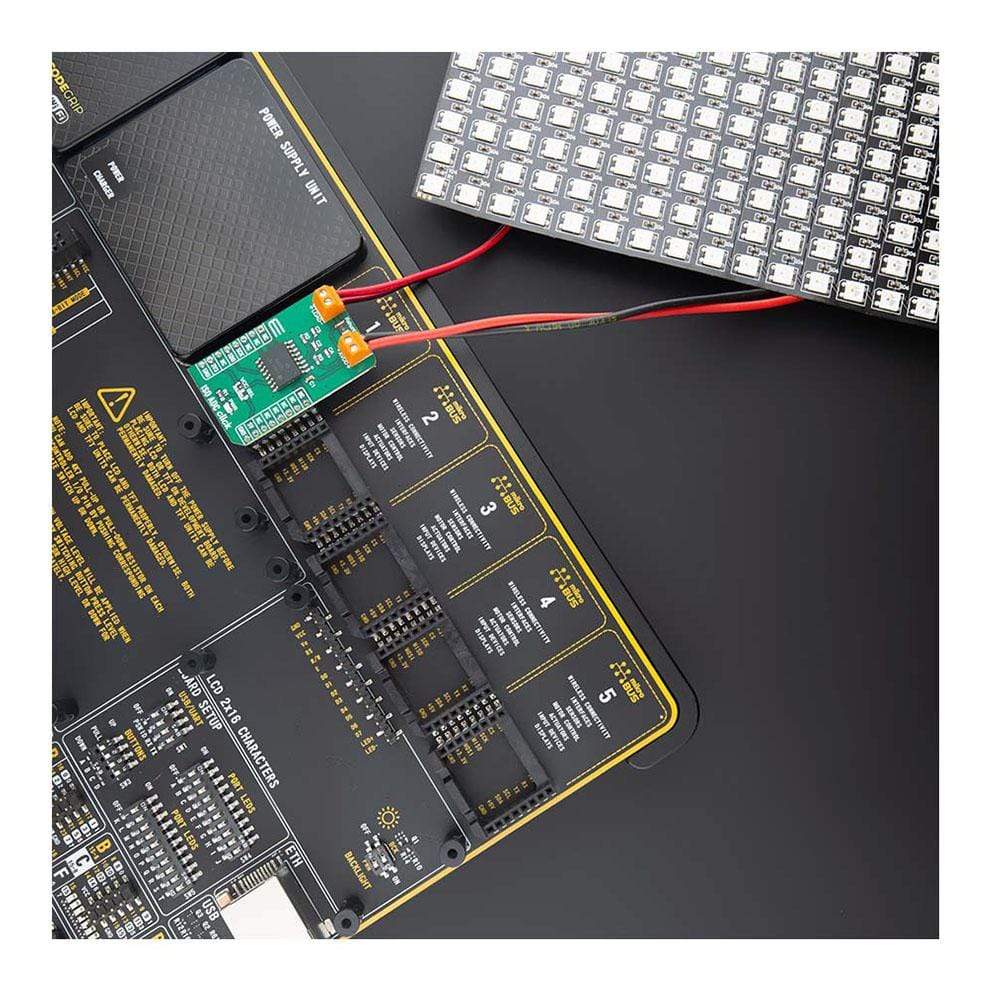
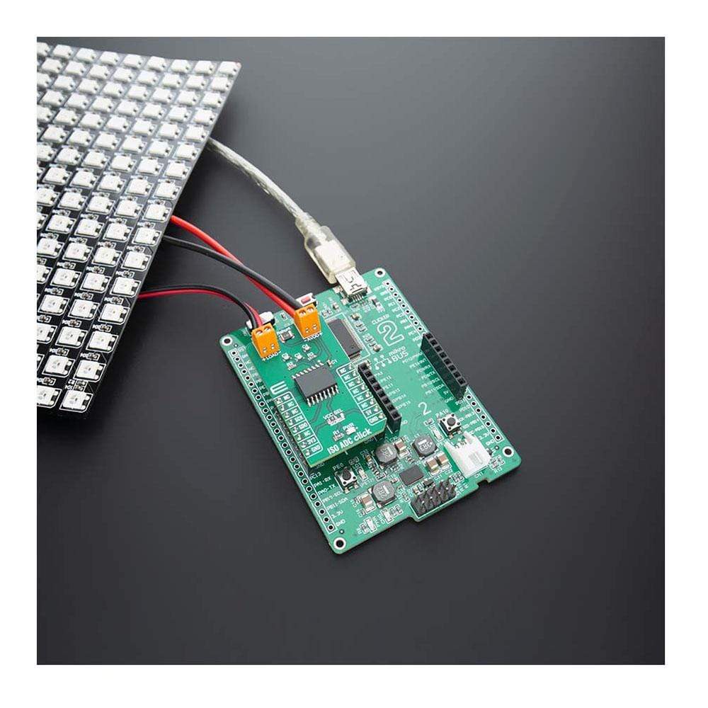
The ISO ADC Click Board™ is supported by a mikroSDK compliant library, which includes functions that simplify software development. This Click Board™ comes as a fully tested product, ready to be used on a system equipped with the mikroBUS™ socket.
Downloads
L' ISO ADC Click Board™ est un dispositif de mesure de shunt de courant à carte complémentaire avec modulateur delta-sigma isolé. Ce Click Board™ est basé sur l'AMC1204BDWR et fournit une solution monopuce pour mesurer le petit signal d'une résistance shunt à travers une barrière isolée de Texas Instruments. L'ISO ADC Click contient une résistance shunt, ces types de résistances sont généralement utilisés pour détecter les courants dans les onduleurs de commande de moteur, les systèmes de production d'énergie verte et d'autres applications industrielles.
La carte Click Board™ ISO ADC est prise en charge par une bibliothèque compatible mikroSDK, qui comprend des fonctions qui simplifient le développement logiciel. Cette carte Click Board™ est un produit entièrement testé, prêt à être utilisé sur un système équipé du socket mikroBUS™.
| General Information | |
|---|---|
Part Number (SKU) |
MIKROE-4088
|
Manufacturer |
|
| Physical and Mechanical | |
Weight |
0.023 kg
|
| Other | |
EAN |
8606018717309
|
Frequently Asked Questions
Have a Question?
Be the first to ask a question about this.