Tableau à clic Compass 3
Overview
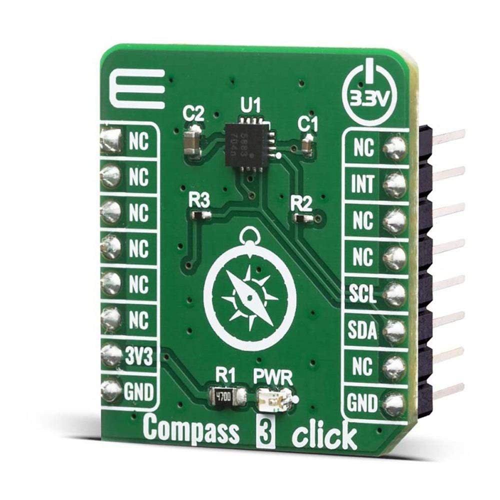
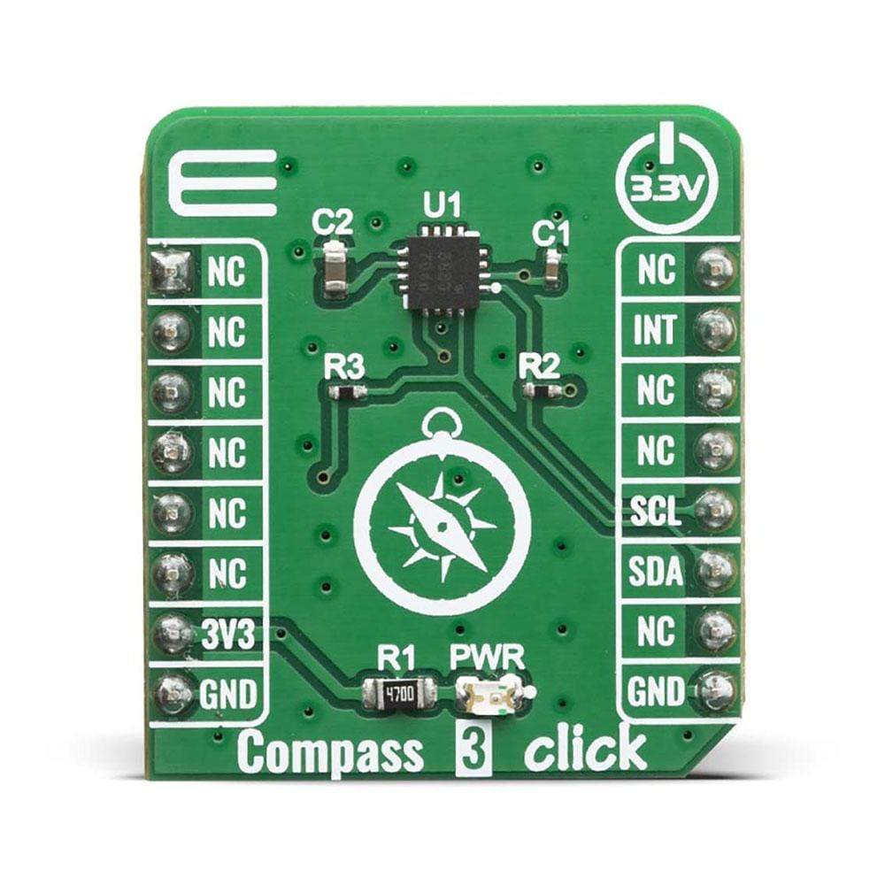
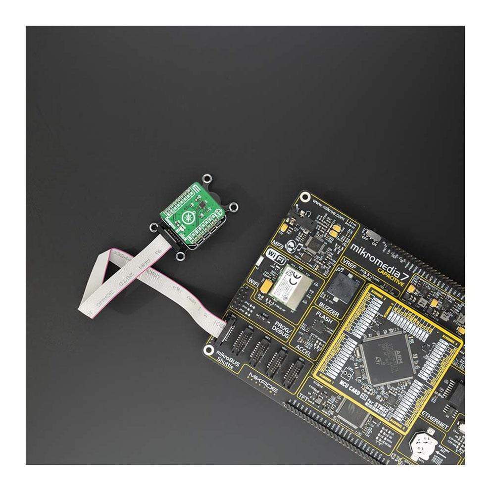
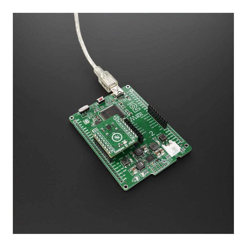
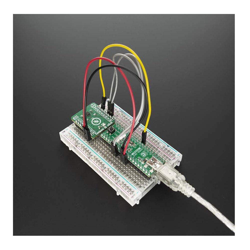
Le Tableau à cliquer Compass 3™ est une carte d'extension qui peut mesurer le champ magnétique à trois axes, ce qui est parfait pour une mise en œuvre dans des applications telles que les boussoles électriques. Cette carte est équipée du MMC5883MA, un capteur magnétique à 3 axes complet avec traitement du signal de MEMSIC. Pour obtenir les données de mesure du capteur du champ magnétique et de la température, un protocole I2C est utilisé.
La principale caractéristique du capteur est la capacité de mesurer des champs magnétiques dans la plage pleine échelle de 8 Gauss (G), avec une résolution de 0,25 mG par LSB en mode de fonctionnement 16 bits et un niveau de bruit RMS total de 0,4 mG, permettant une précision de cap de 1º dans les applications de boussole électronique.
Le tableau à clic Compass 3™ convient aux applications telles que la boussole électrique, la détection de position, la mesure générale du champ magnétique et plus encore.
How Does The Compass 3 Click Board™ Work?
The Compass 3 Click Board™ uses the MMC5883MA, a complete 3-axis magnetic sensor with on-chip signal processing and integrated I2C bus suitable for use in various applications, from MEMSIC. The device eliminates the need for A/D converters or timing resources by being directly connected to a microprocessor. It can measure magnetic fields within the full scale range of ±8Gauss (G), with 0.25mG per LSB resolution at 16bits operation mode and 0.4mG total RMS noise level, enabling heading accuracy of ±1° in electronic compass applications.
An integrated SET/RESET function provides for the elimination of error due to Null Field output change with temperature. Temperature information from the integrated temperature sensor is available over the I2C Interface.
The SET/RESET function can be performed for each measurement, periodically, or when the temperature changes by a predetermined amount as the specific application requires. In addition, the SET/RESET function clears the sensors of any residual magnetic polarization resulting from exposure to strong external magnets. The MMC5883MA is packaged in a low profile LGA package (3.0 x 3.0 x 1.0 mm) and an operating temperature range from -40°C to +85°C. The MMC5883MA provides an I2C digital output with 400 kHz, fast mode operation.
The Compass 3 Click Board™ is designed to be operated only with a 3.3V logic level. A proper logic voltage level conversion should be performed before the Click board™ is used with MCUs with different logic levels.
SPECIFICATIONS
Type | Compass,Magnetic |
Applications | The Compass 3 Click Board™ be used in electronic compass and navigation, position sensing or general purpose magnetic field measurements. |
On-board modules | Compass 3 Click uses the MMC5883MA IC, a complete 3-axis magnetic sensor with on-chip signal processing, from Memsic Inc. |
Key Features | Measuring of magnetic field within the full scale range of ±8Gauss (G), 16bits resolution, 0.25mG per LSB sensitivity, heading accuracy of ±1° |
Interface | I2C |
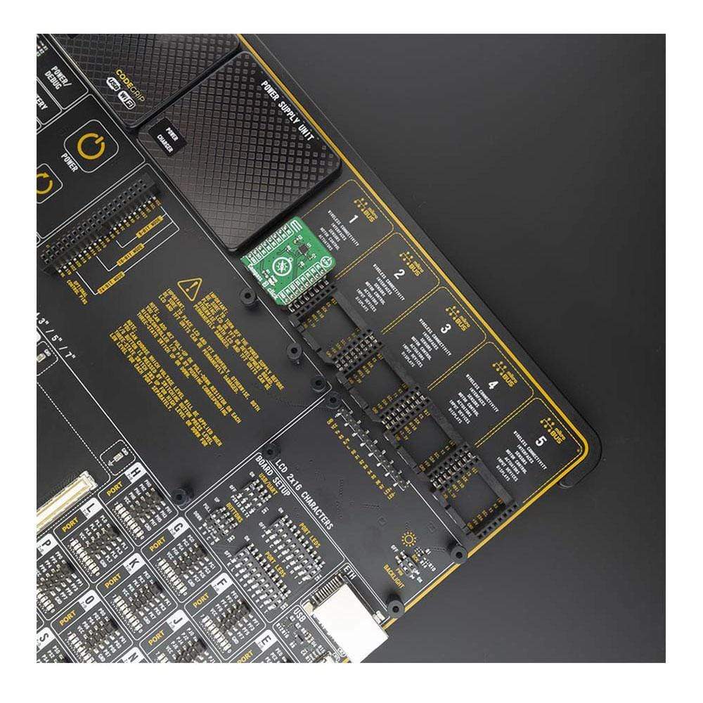
Compatibility | mikroBUS |
Click board size | S (28.6 x 25.4 mm) |
Input Voltage | 3.3V |
PINOUT DIAGRAM
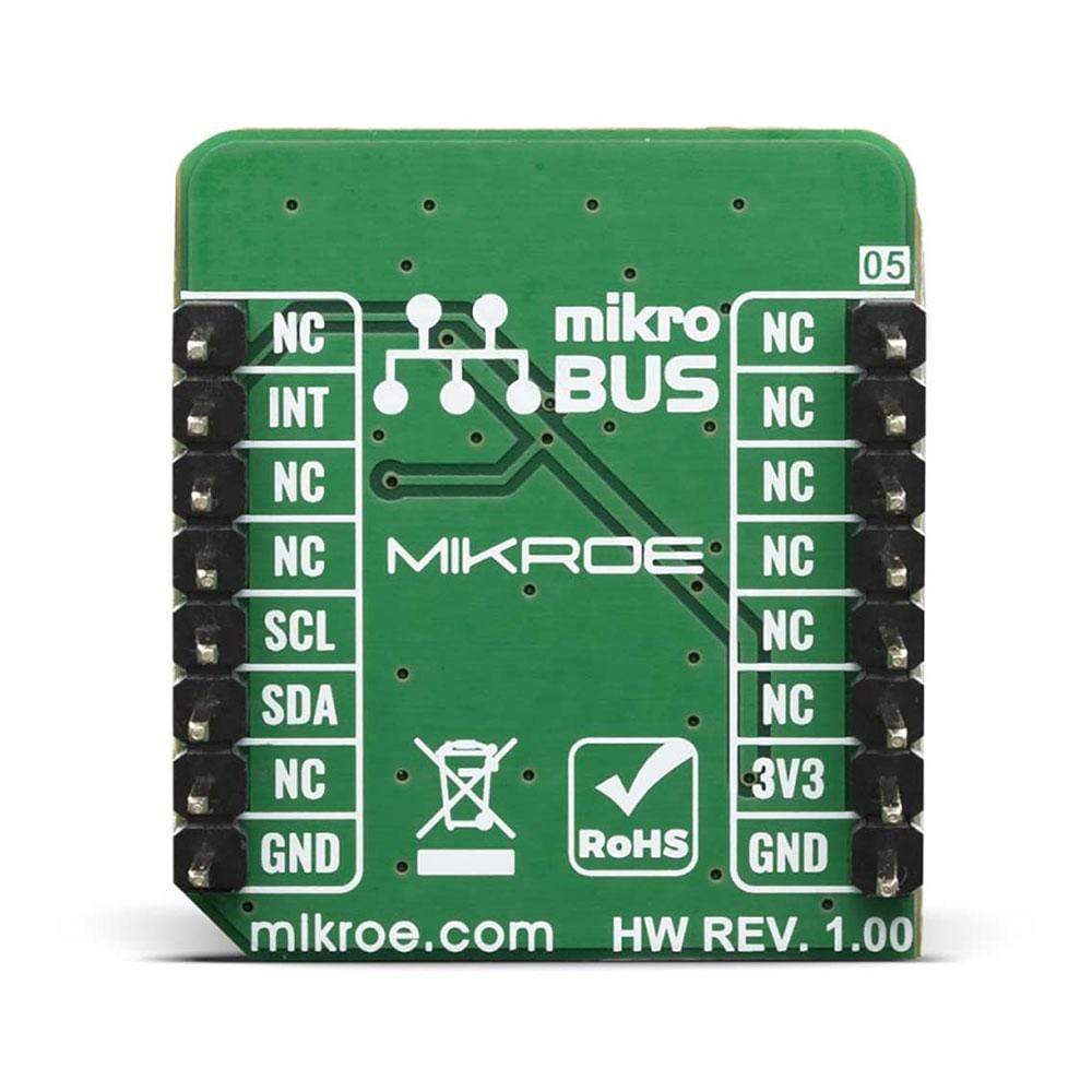
This table shows how the pinout for the Compass 3 Click Board™ corresponds to the pinout on the mikroBUS™ socket (the latter shown in the two middle columns).
Notes | Pin | Pin | Notes | ||||
---|---|---|---|---|---|---|---|
NC | 1 | AN | PWM | 16 | NC | ||
NC | 2 | RST | INT | 15 | INT | Interrupt | |
NC | 3 | CS | RX | 14 | NC | ||
NC | 4 | SCK | TX | 13 | NC | ||
NC | 5 | MISO | SCL | 12 | SCL | I2C Clock | |
NC | 6 | MOSI | SDA | 11 | SDA | I2C Data | |
Power Supply | 3.3V | 7 | 3.3V | 5V | 10 | NC | |
Ground | GND | 8 | GND | GND | 9 | GND | Ground |
ONBOARD SETTINGS AND INDICATORS
Label | Name | Default | Description |
---|---|---|---|
LD1 | PWR | - | Power LED Indicator |
COMPASS 3 CLICK ELECTRICAL SPECIFICATIONS
Description | Min | Typ | Max | Unit |
---|---|---|---|---|
Field Range (Each Axis) | - | ±8 | - | G |
Supply Voltage | 2.16 | 3.3 | 3.6 | V |
Operating Temperature Range | -40 | - | 85 | °C |
Software Support
We provide a library for the Compass 3 Click Board™ on our LibStock page, as well as a demo application (example), developed using MikroElektronika compilers. The demo can run on all the main MikroElektronika development boards.
Library Description
This library holds functions that can be used to read, write and measure magnetic field and temperature.
Key Functions
void compass3_write_byte ( uint8_t reg_adr, uint8_t data_in );
- Writes 8-bit data into register defined by 8-bit register address.void compass3_full_measurement ( float *x_val, float *y_val, float *z_val );
- Measures magnetic field surrounding the device.float compass3_read_temp ( );
- Function is used to measure temperature.
Example Description
The application is composed of three sections :
- System Initialization - Initializes I2C module, LOG and GPIO structures, sets INT pin as input.
- Application Initialization - Initalizes I2C driver, applies default setup and writes an initial log.
- Application Task - (code snippet) This example demonstrates the use of the Compass 3 Click Board™ by measuring the magnetic field surrounding the device.
void application_task ( ) { if( compass3_check_int () == COMPASS3_INTERRUPT ) { compass3_full_measurement ( &x_val, &y_val, &z_val ); FloatToStr( x_val, log_txt ); mikrobus_logWrite( " X-axis: ", _LOG_TEXT ); mikrobus_logWrite( log_txt, _LOG_TEXT ); mikrobus_logWrite( "mG", _LOG_LINE ); FloatToStr( y_val, log_txt ); mikrobus_logWrite( " Y-axis: ", _LOG_TEXT ); mikrobus_logWrite( log_txt, _LOG_TEXT ); mikrobus_logWrite( "mG", _LOG_LINE ); FloatToStr( z_val, log_txt ); mikrobus_logWrite( " Z-axis: ", _LOG_TEXT ); mikrobus_logWrite( log_txt, _LOG_TEXT ); mikrobus_logWrite( "mG", _LOG_LINE ); Delay_ms( 1000 ); mikrobus_logWrite( "--------------------", _LOG_LINE ); } }
The full application code, and ready to use projects can be found on our LibStock page.
Other mikroE Libraries used in the example:
- I2C
- UART
- Conversions
Additional Notes and Information
Depending on the development board you are using, you may need a USB UART Click, USB UART 2 Click or RS232 Click to connect to your PC, for development systems with no UART to USB interface available on the board. The terminal available in all MikroElektronika compilers, or any other terminal application of your choice, can be used to read the message.
MIKROSDK
The Compass 3 Click Board™ is supported with mikroSDK - MikroElektronika Software Development Kit. To ensure proper operation of mikroSDK compliant Click board™ demo applications, mikroSDK should be downloaded from the LibStock and installed for the compiler you are using.
Frequently Asked Questions
Have a Question?
Be the first to ask a question about this.